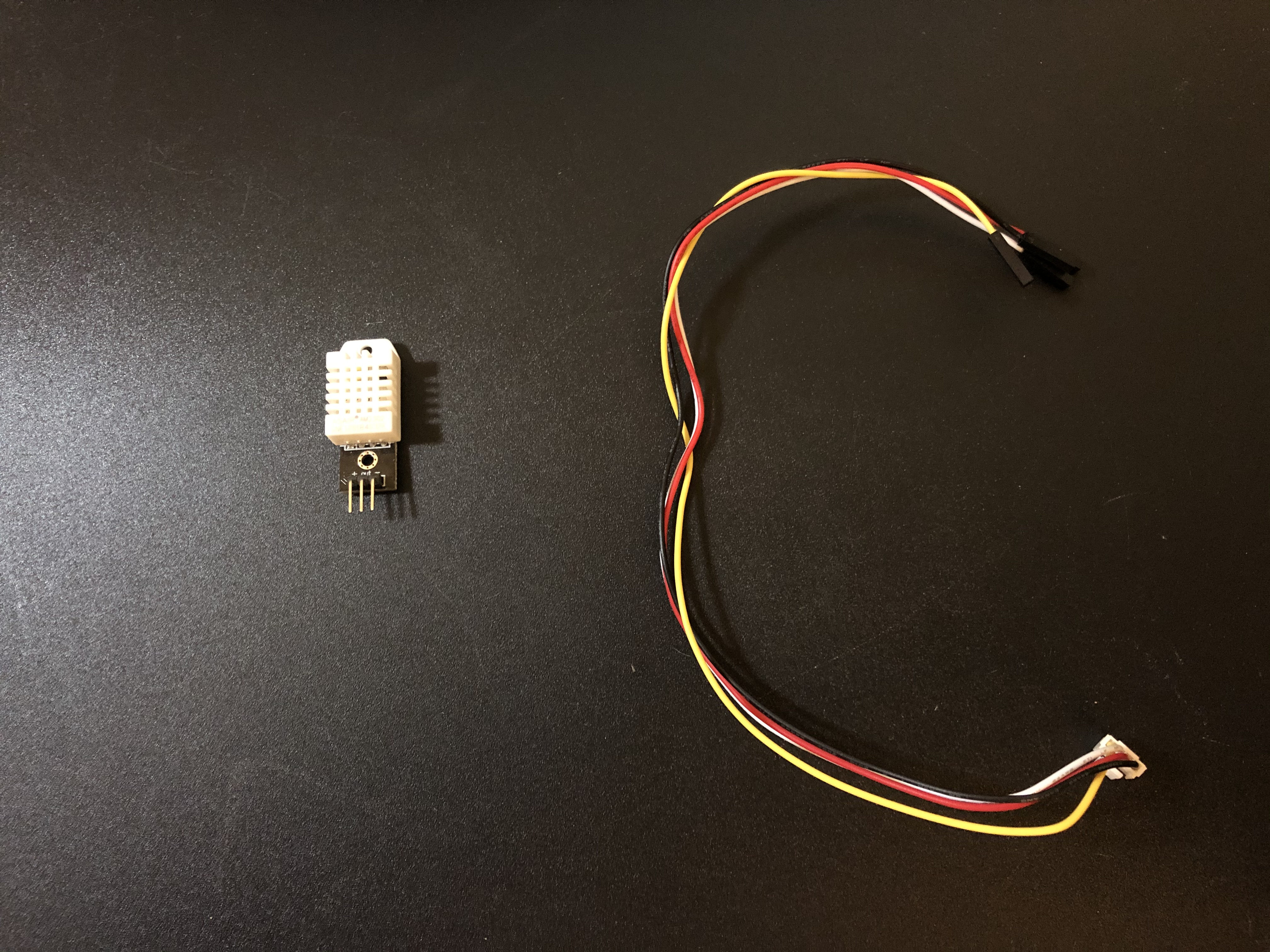
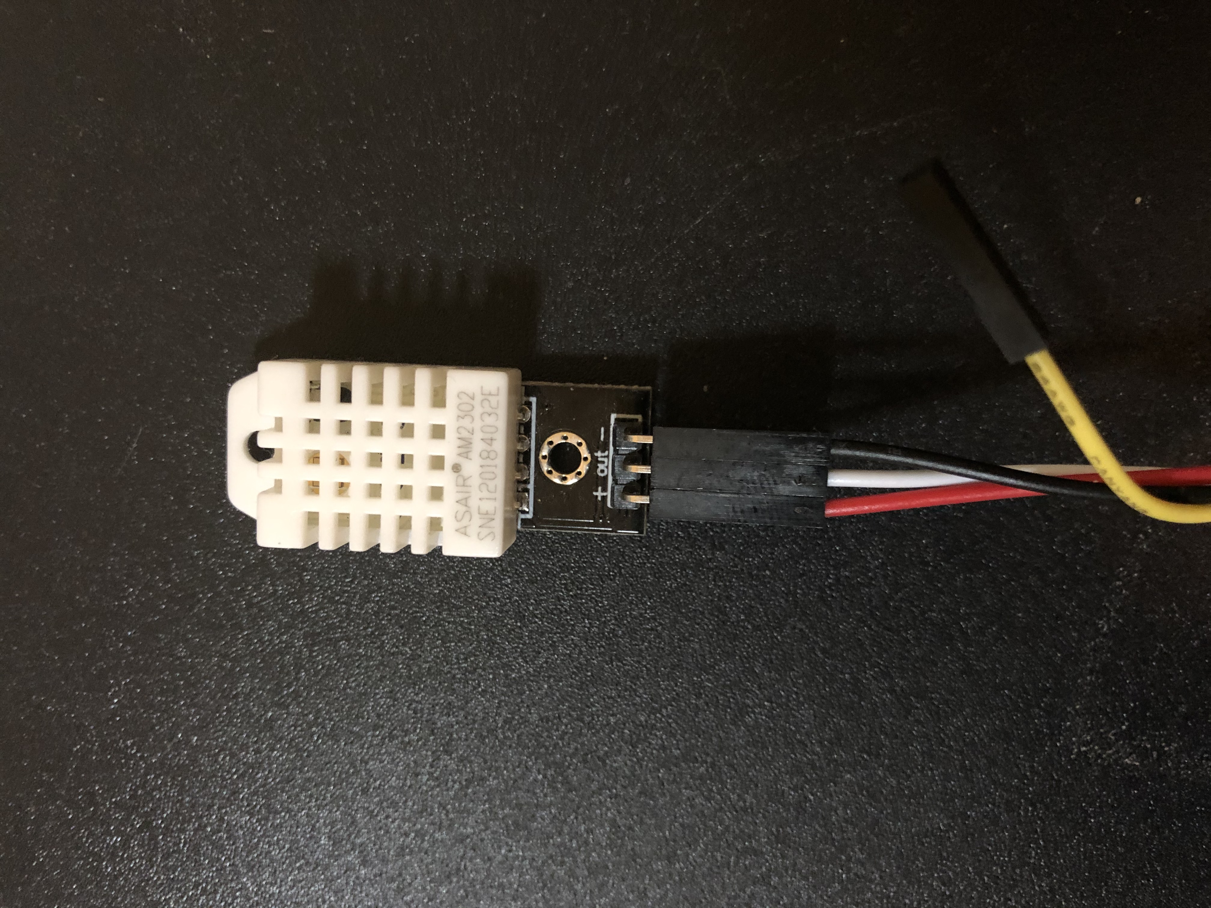
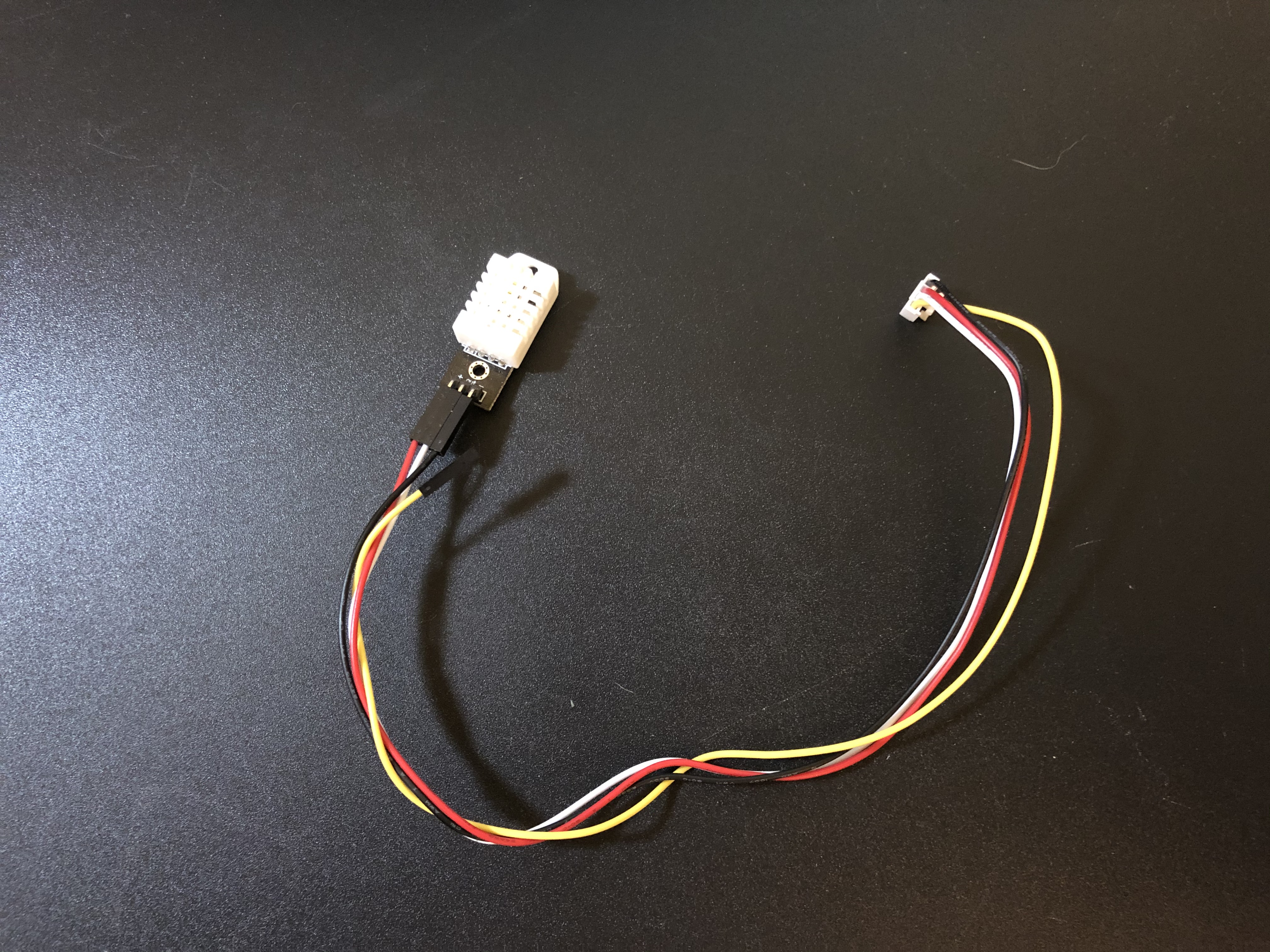
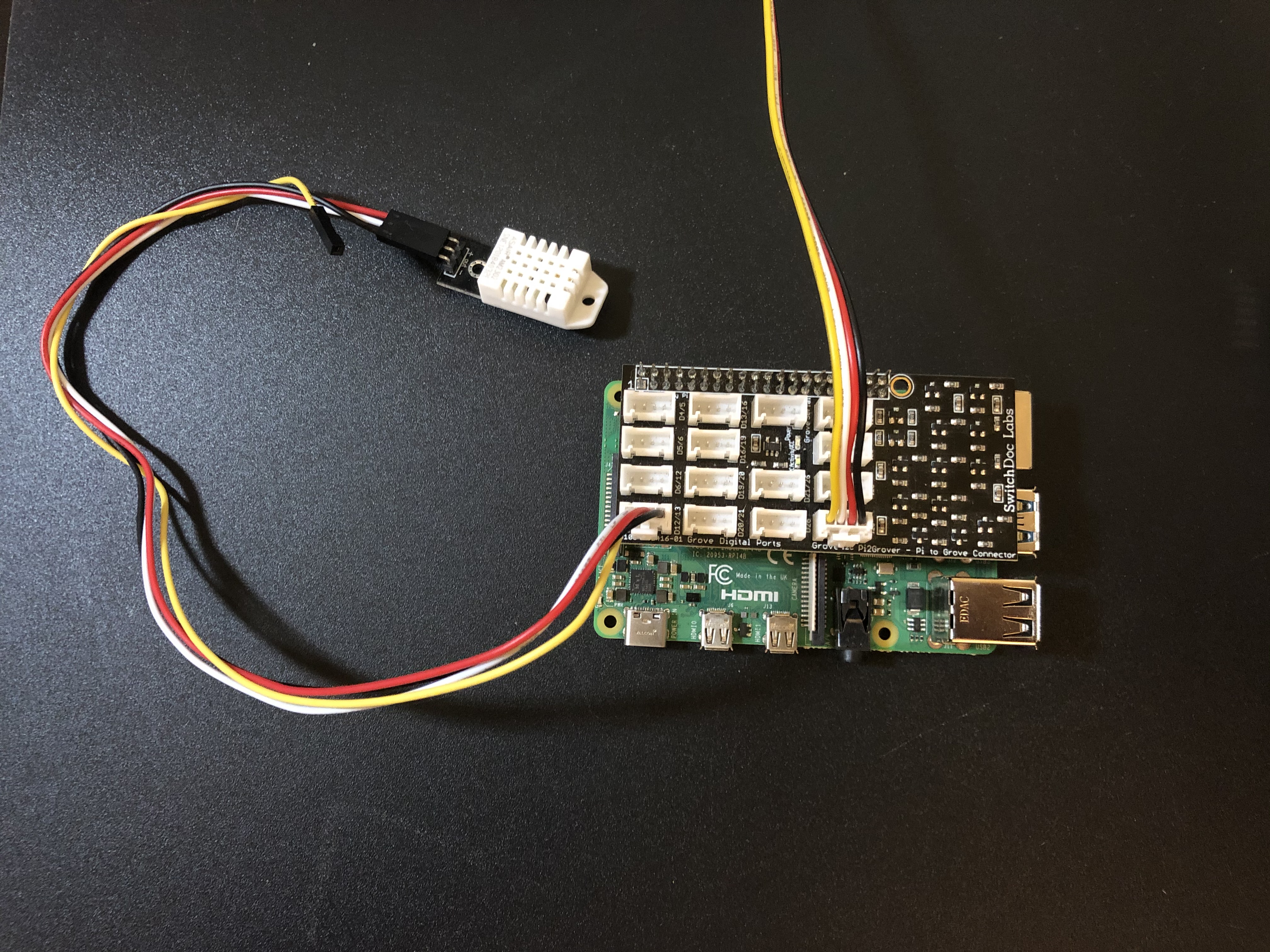
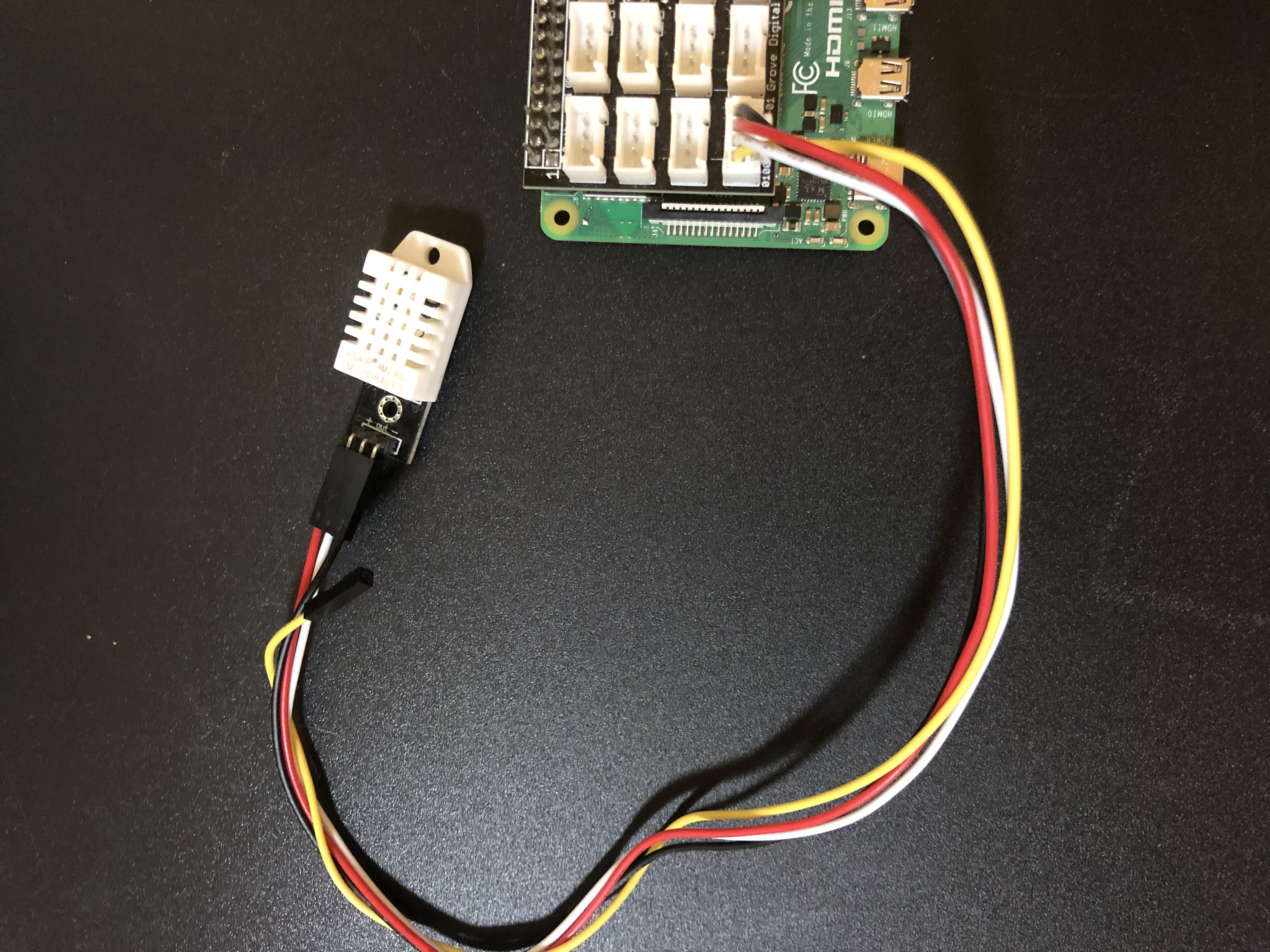
Grab your DHT22 sensor and attach a grove 4-pin connector to it.
Attach the female end of the red wire from the grove 4-pin connector to the male end labeled “+” on the DTH22 sensor.
Attach the female end of the white wire from the grove 4-pin connector to the male end labeled “out” on the DHT22 sensor.
Attach the female end of the black wire from the grove 4-pin connector to the male end labeled “-” on the DHT22 sensor.
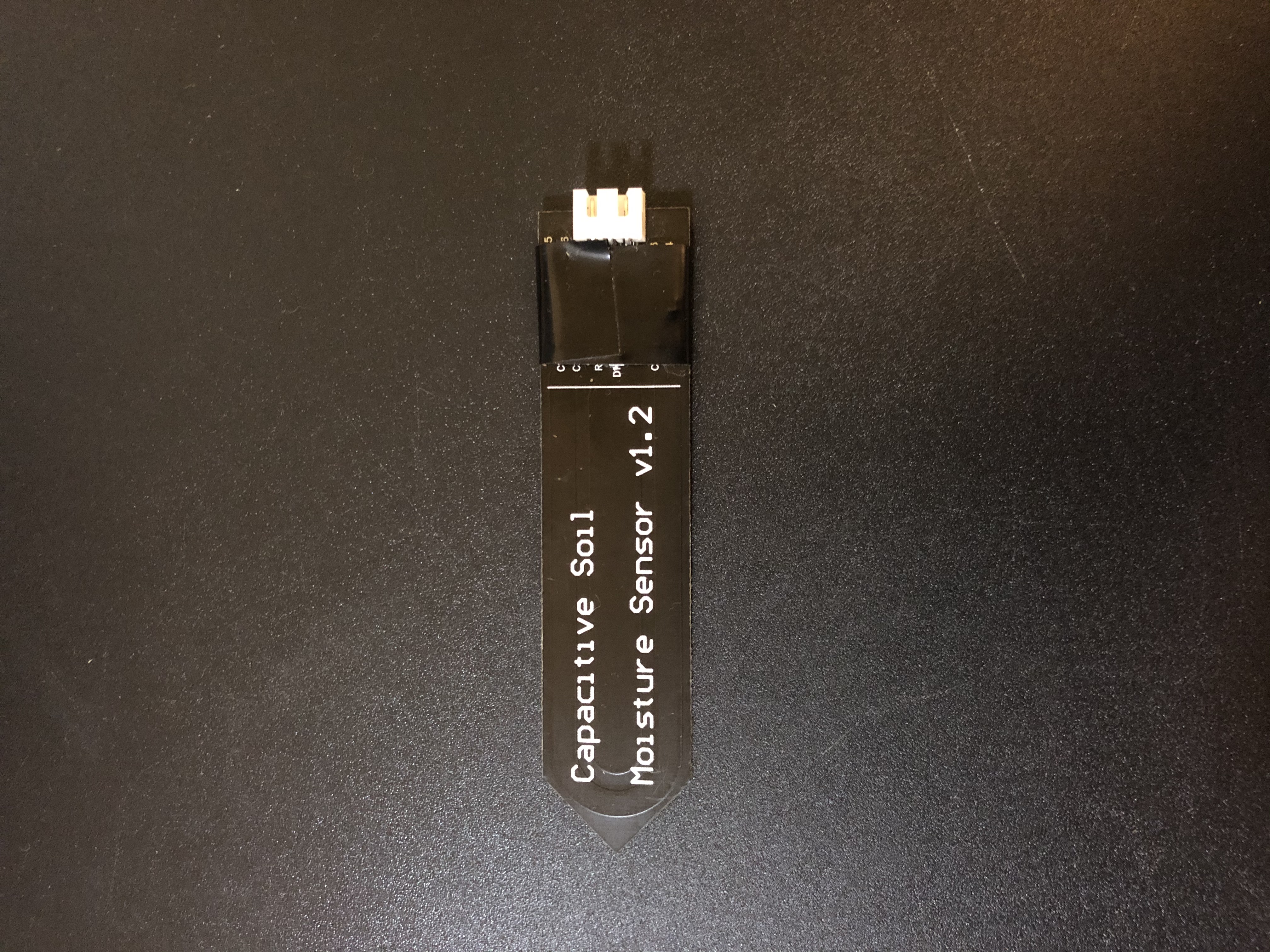
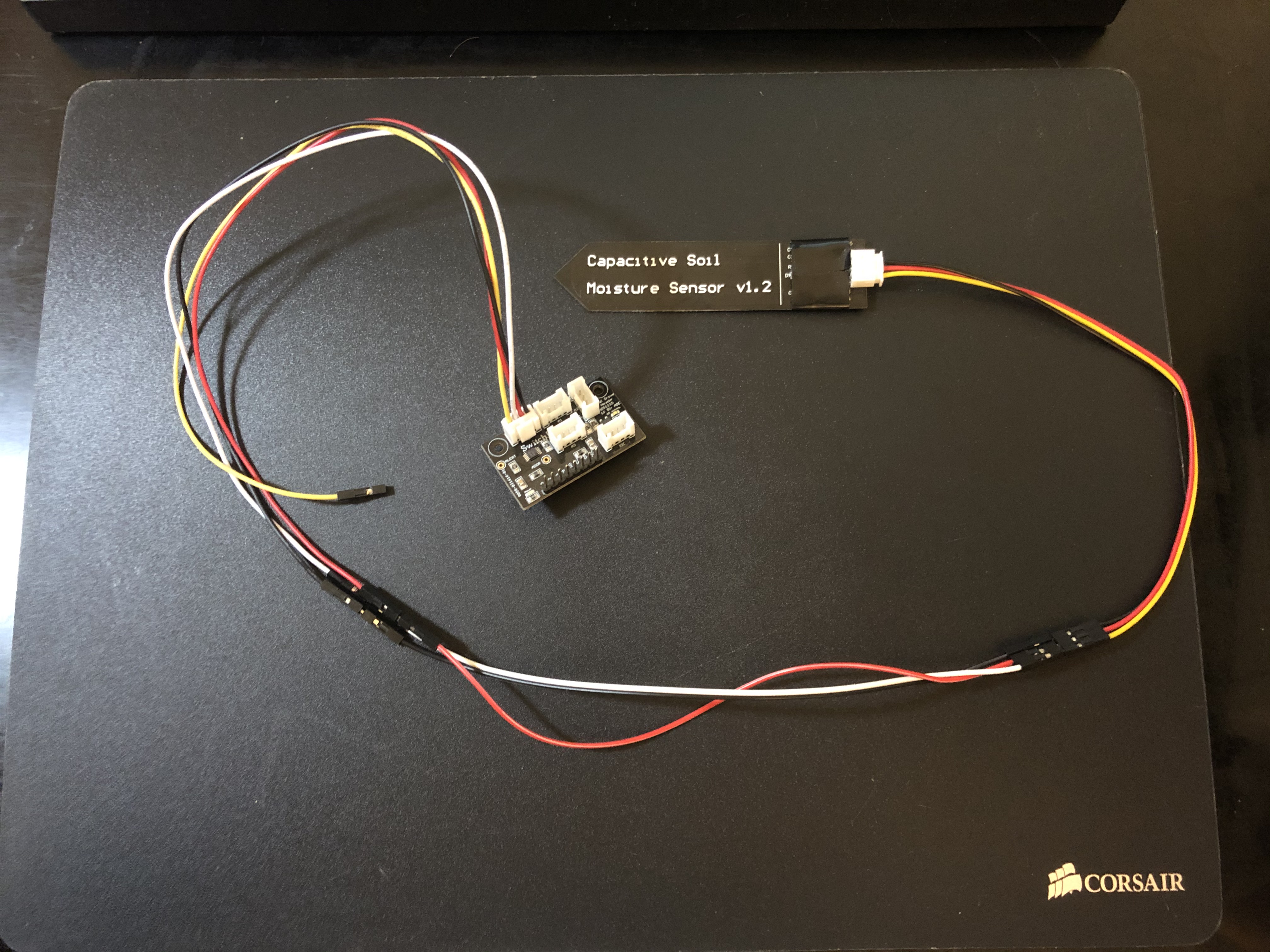
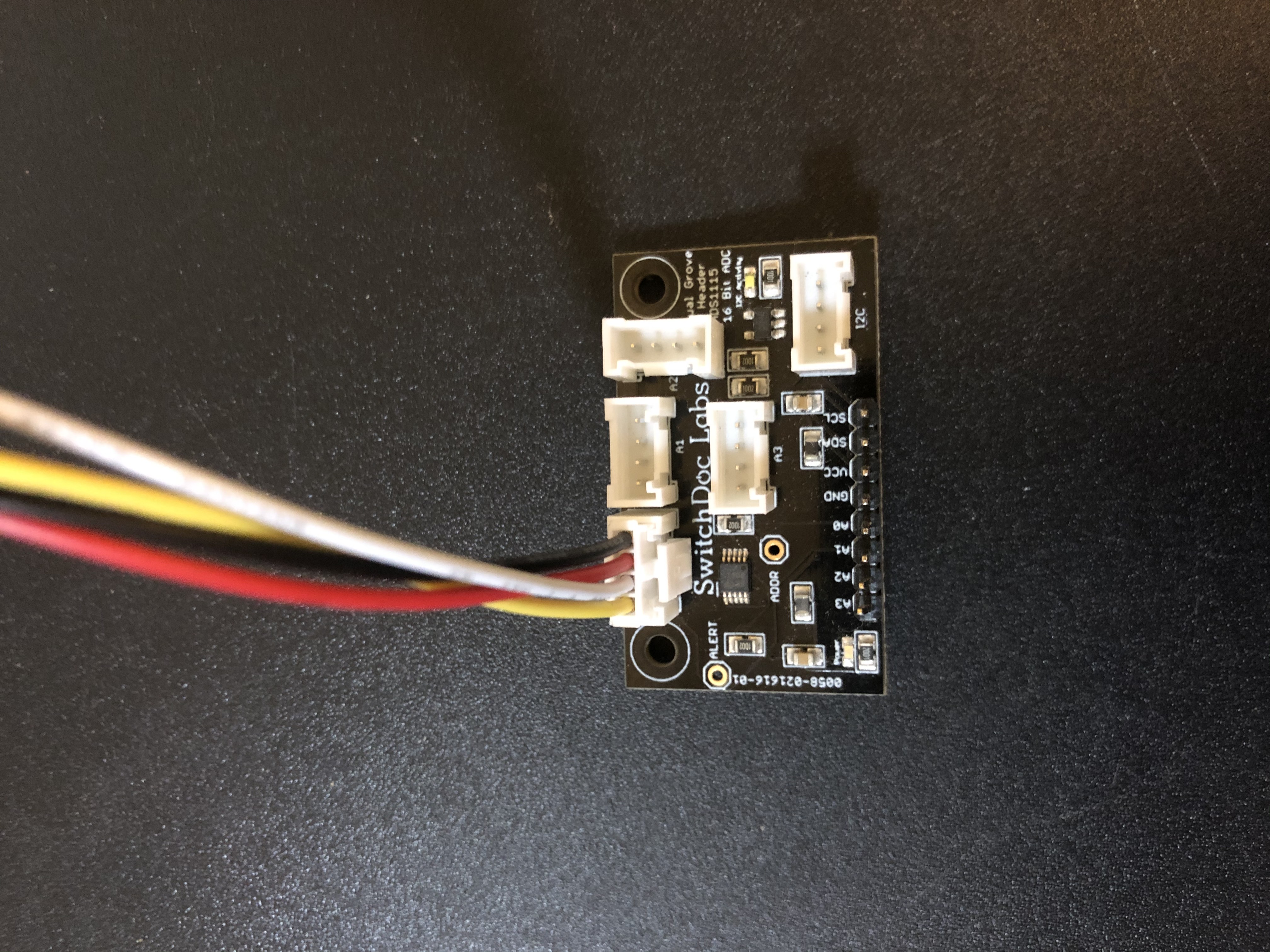
Connect the capcitive soil moisture sensor to the grove analog-to-digital ADS1115 board.
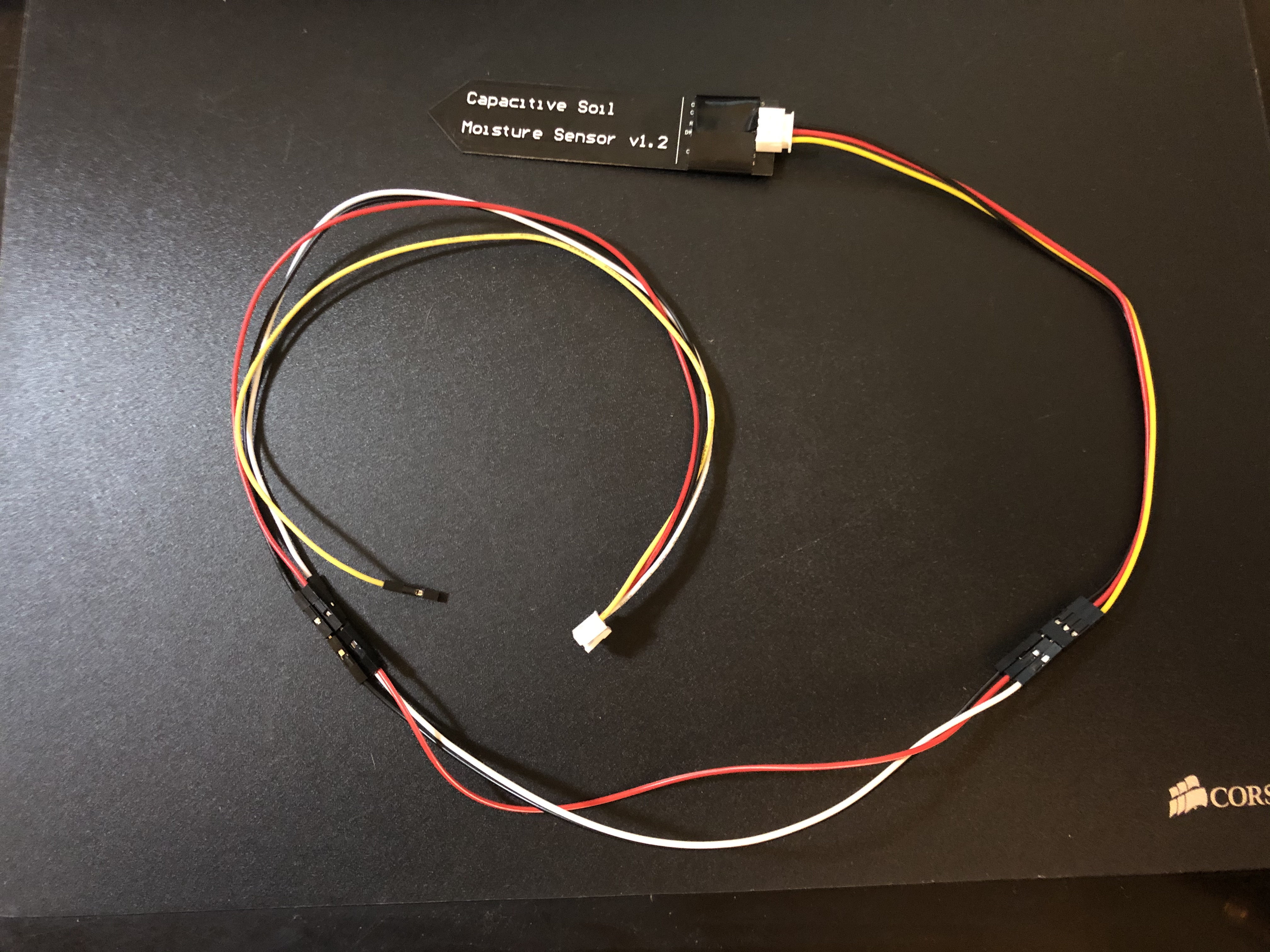
Optional: Wrap electrical tape around the top of the capacitive soil moisture sensor to add protection to the exposed chips on the sensor.
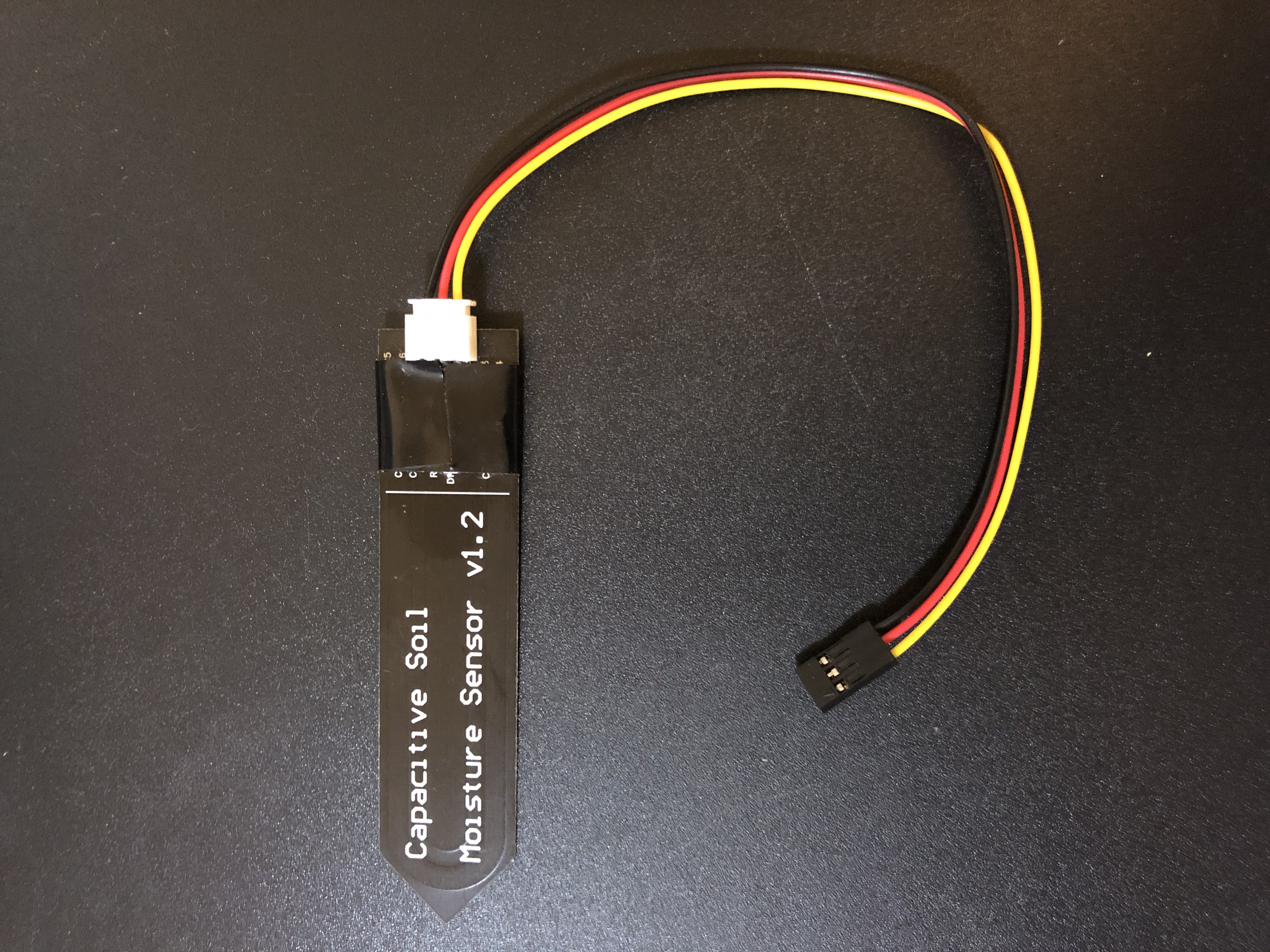
Attach the wires that came with your soil moisture sensor to the top of the soil moisture sensor.
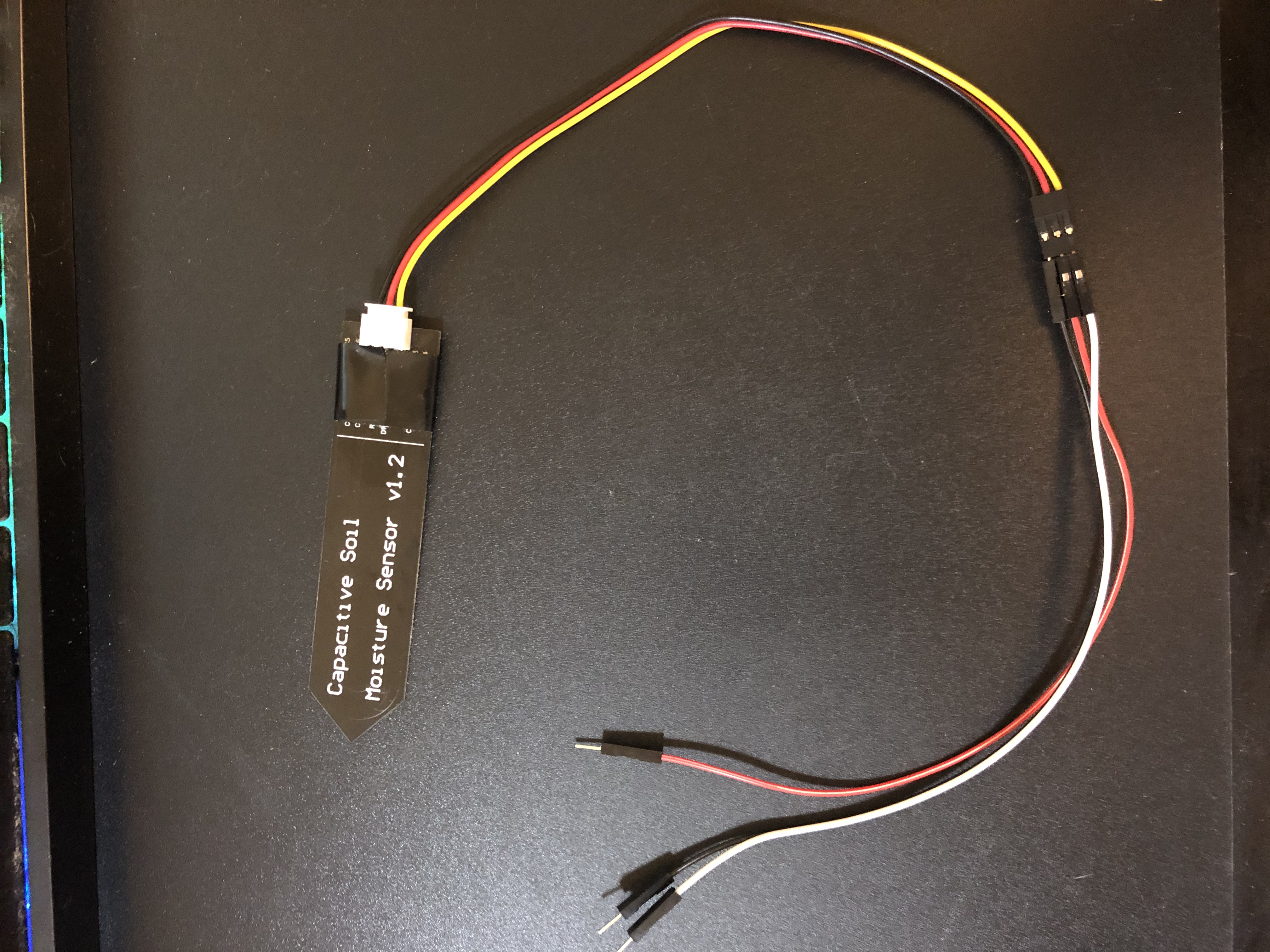
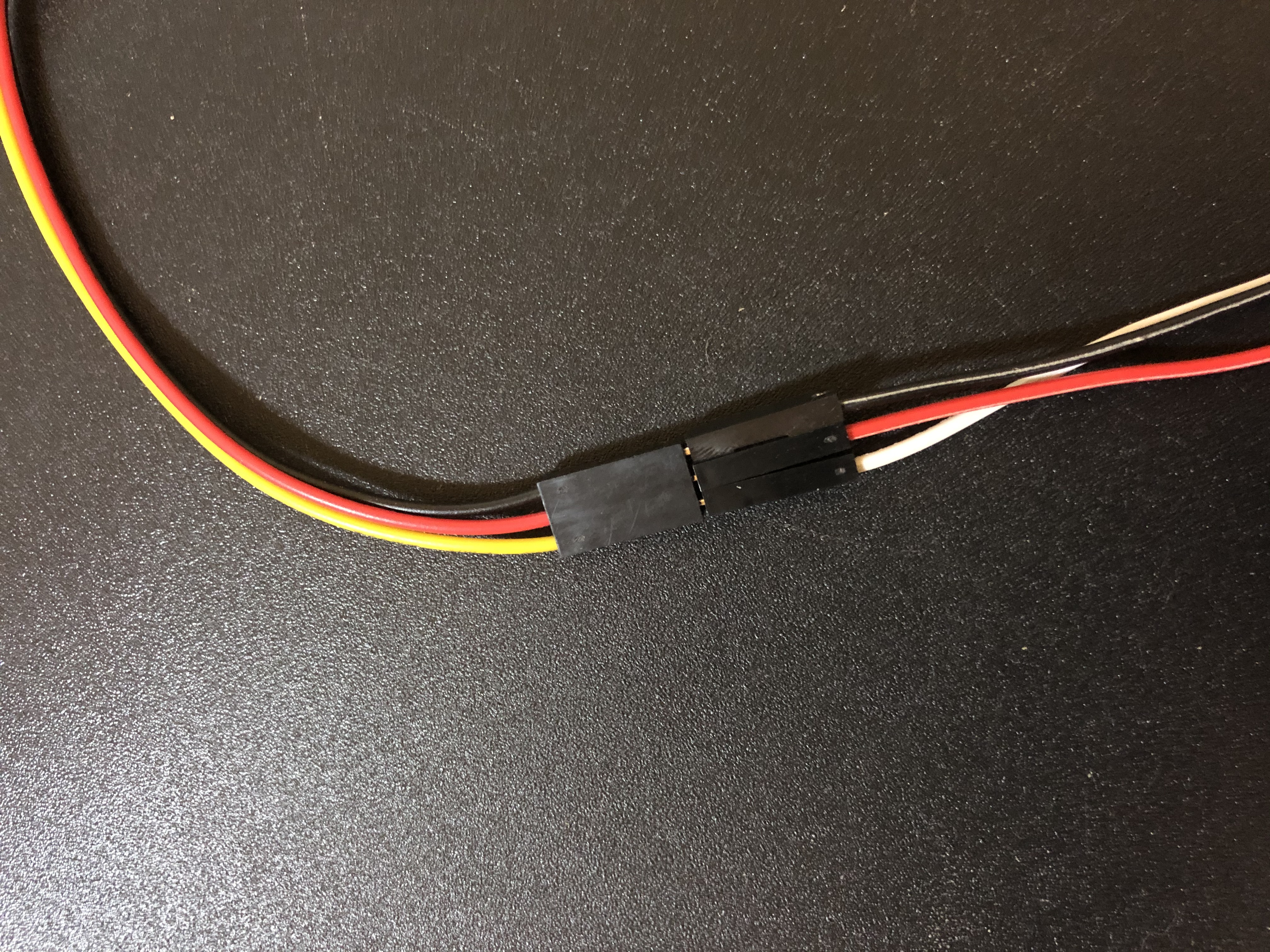
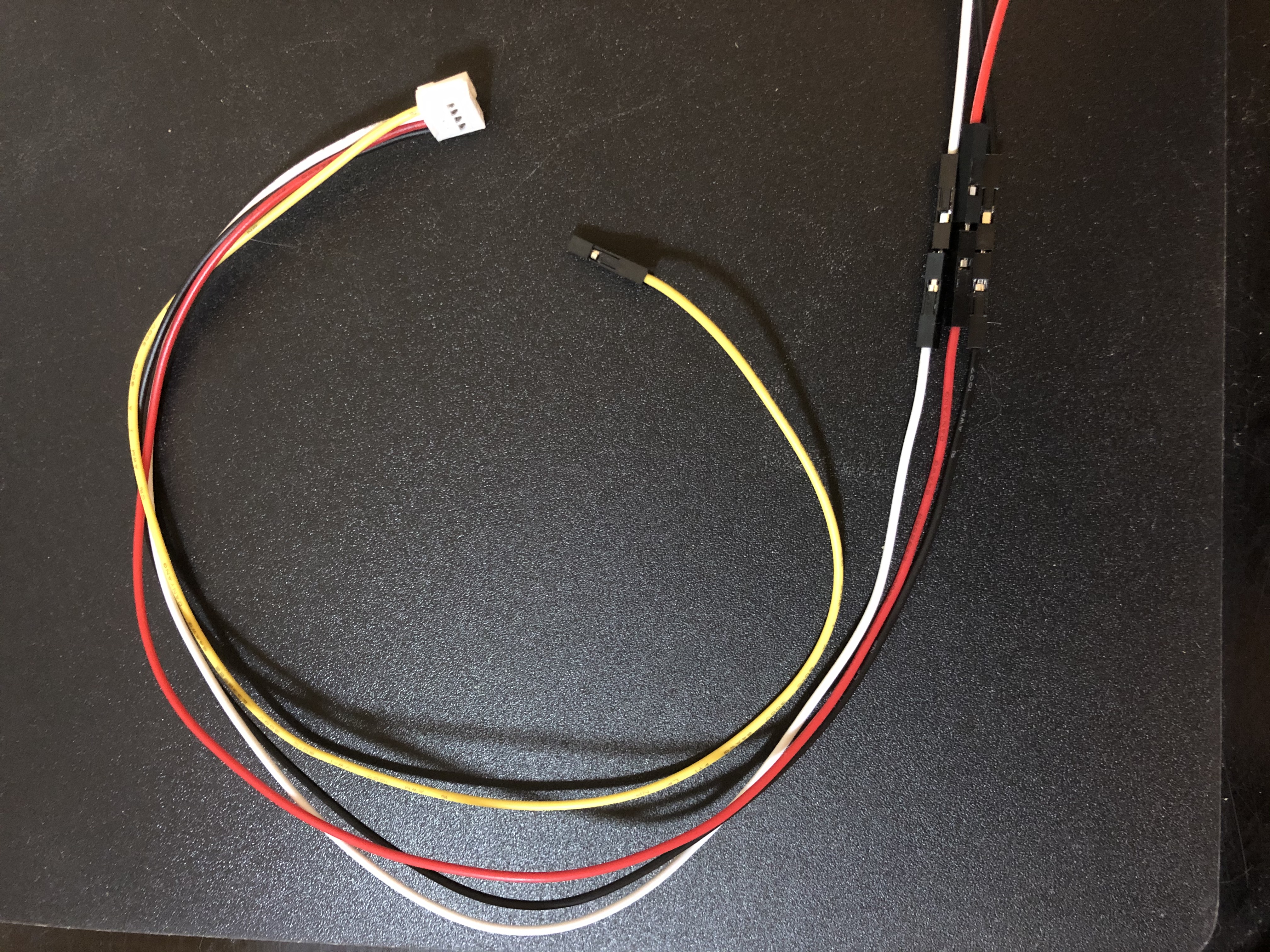
Grab some male to male jumper wires and attach them to the ends of the female connections on the soil sensor.
Grab a grove 4-pin connector to jumper wires and connect that cable to the male ends of the male to male wires you just attached to the soil sensor.
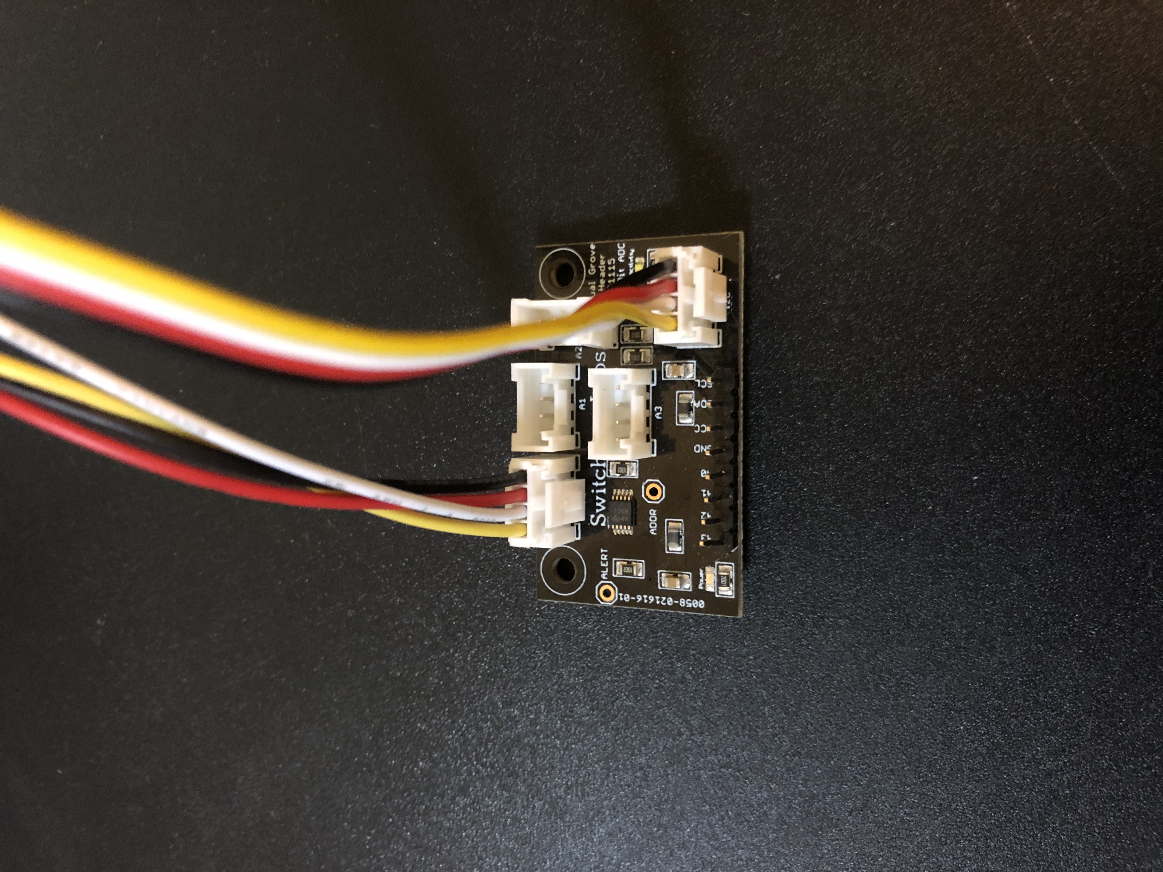
Attach the capacitive soil moisture sensor to the header connector “A0” on the grove analog-to-digital ADS1115 board.
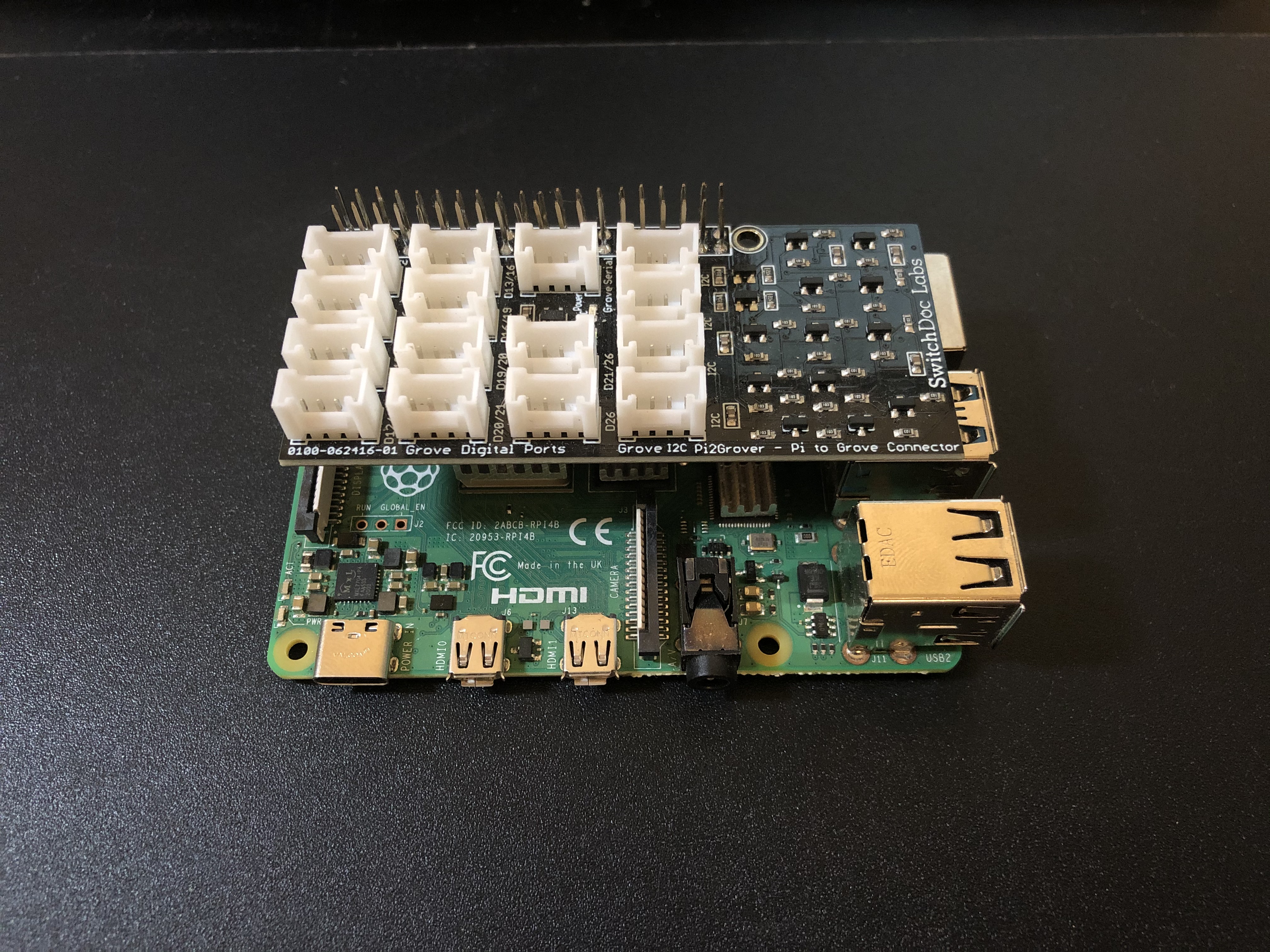
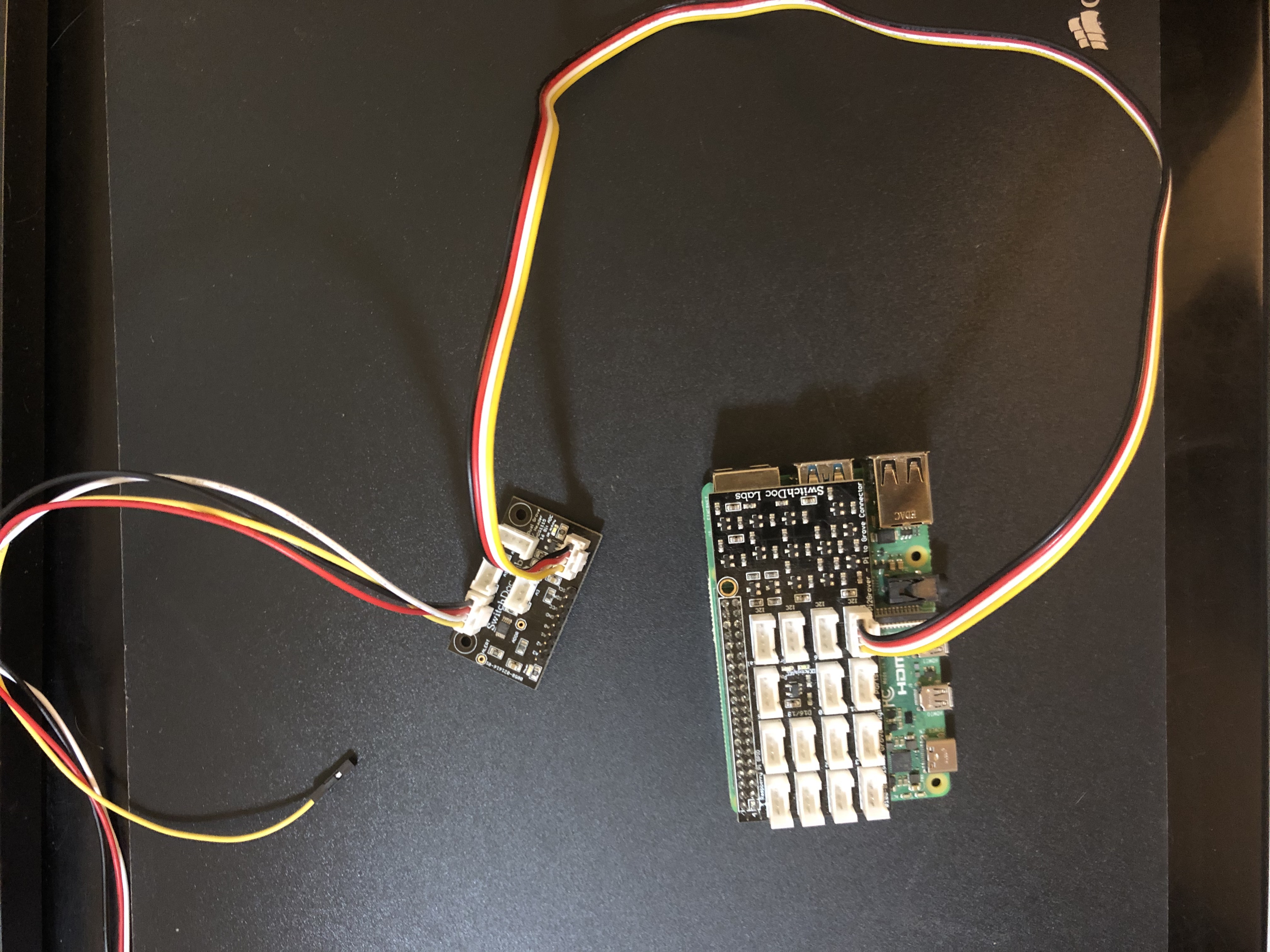
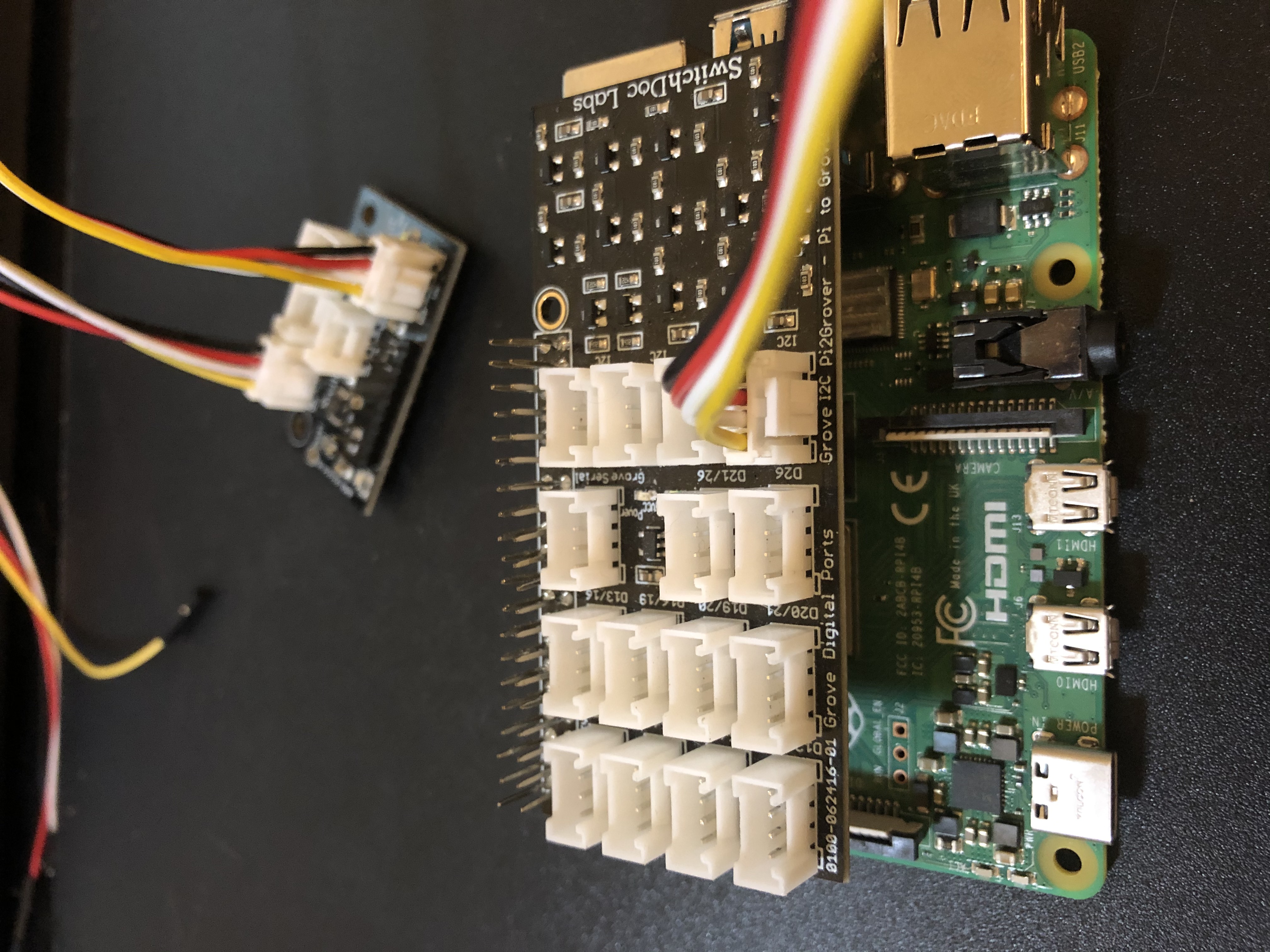
Connect a grove to grove connector to the “I2C” header on the analog-to-digital ADS1115 board to the “I2C” header on the Pi2Grover.
Connect the grove to grove connector to the “I2C” header on the analog-to-digital ADS1115 board.
Connect the other end of the grove to grove connector to the “I2C” header on the Raspberry Pi.
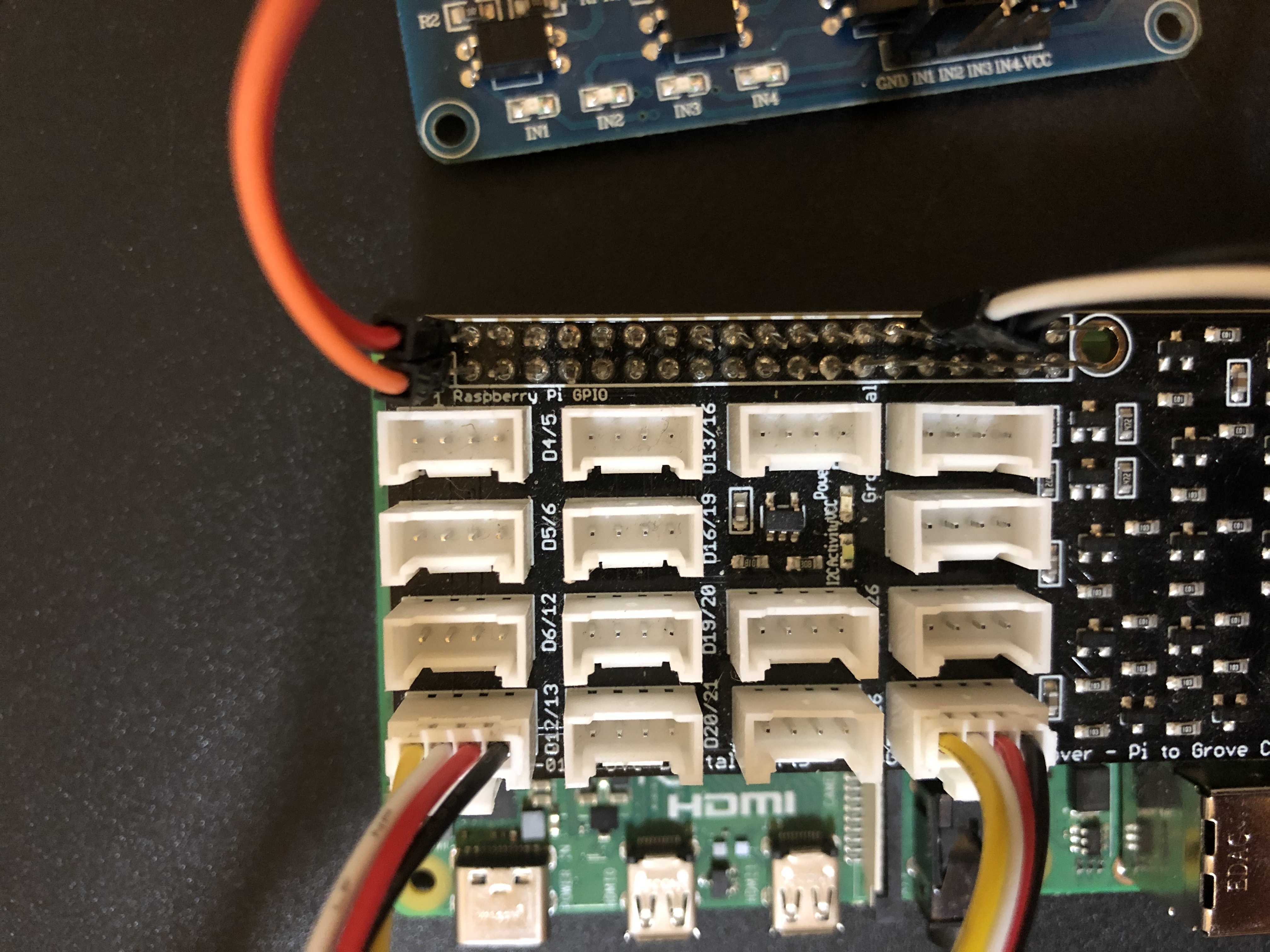
Attach the end of the DHT22 sensor’s grove connector the the header labeled “D12/13” on the Pi2Grover.
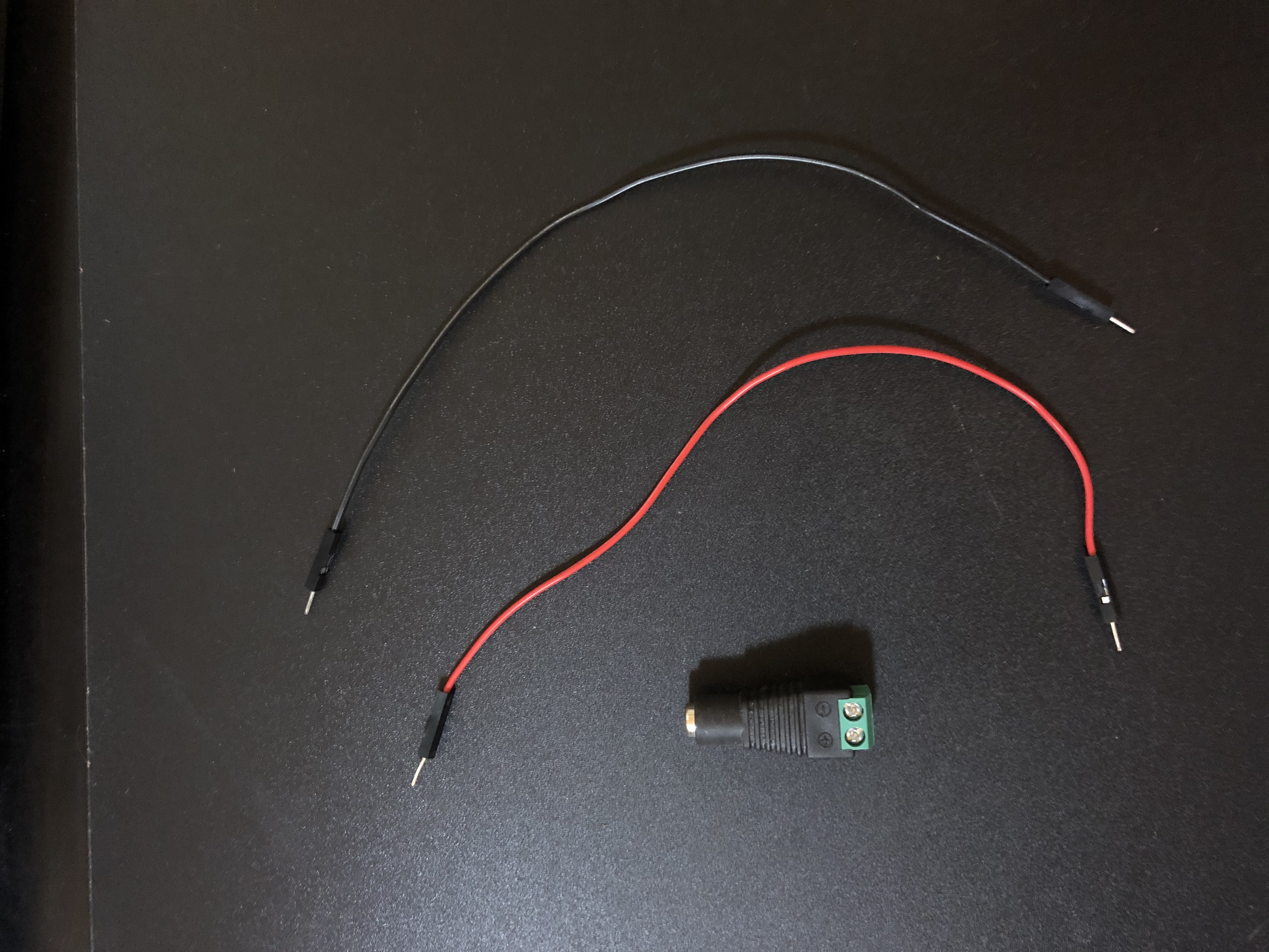
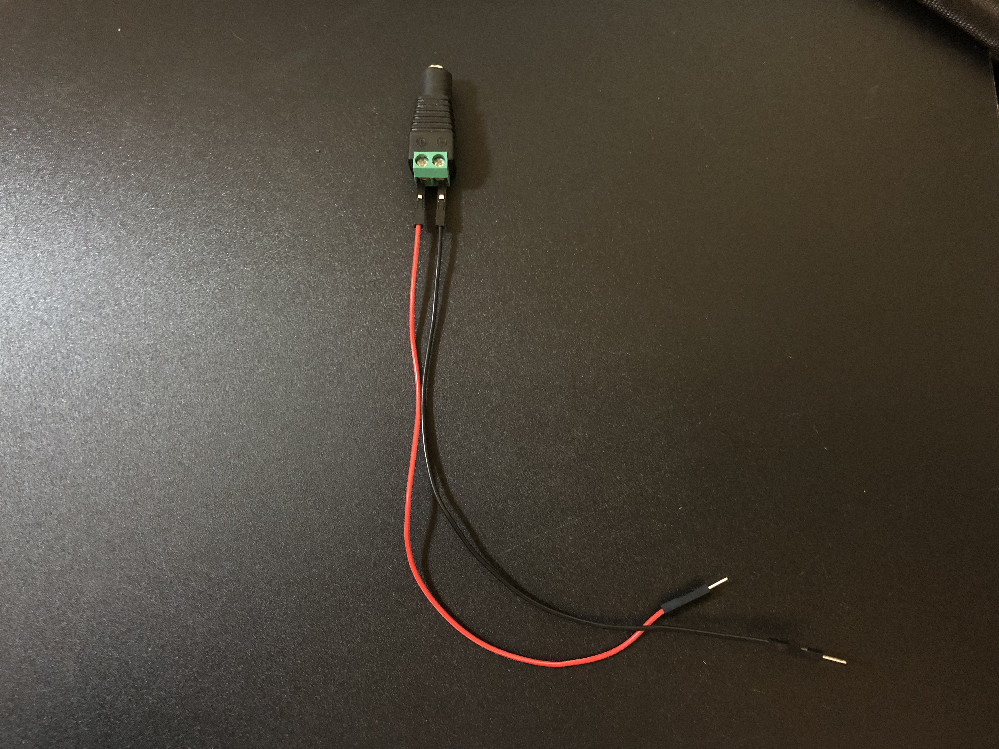
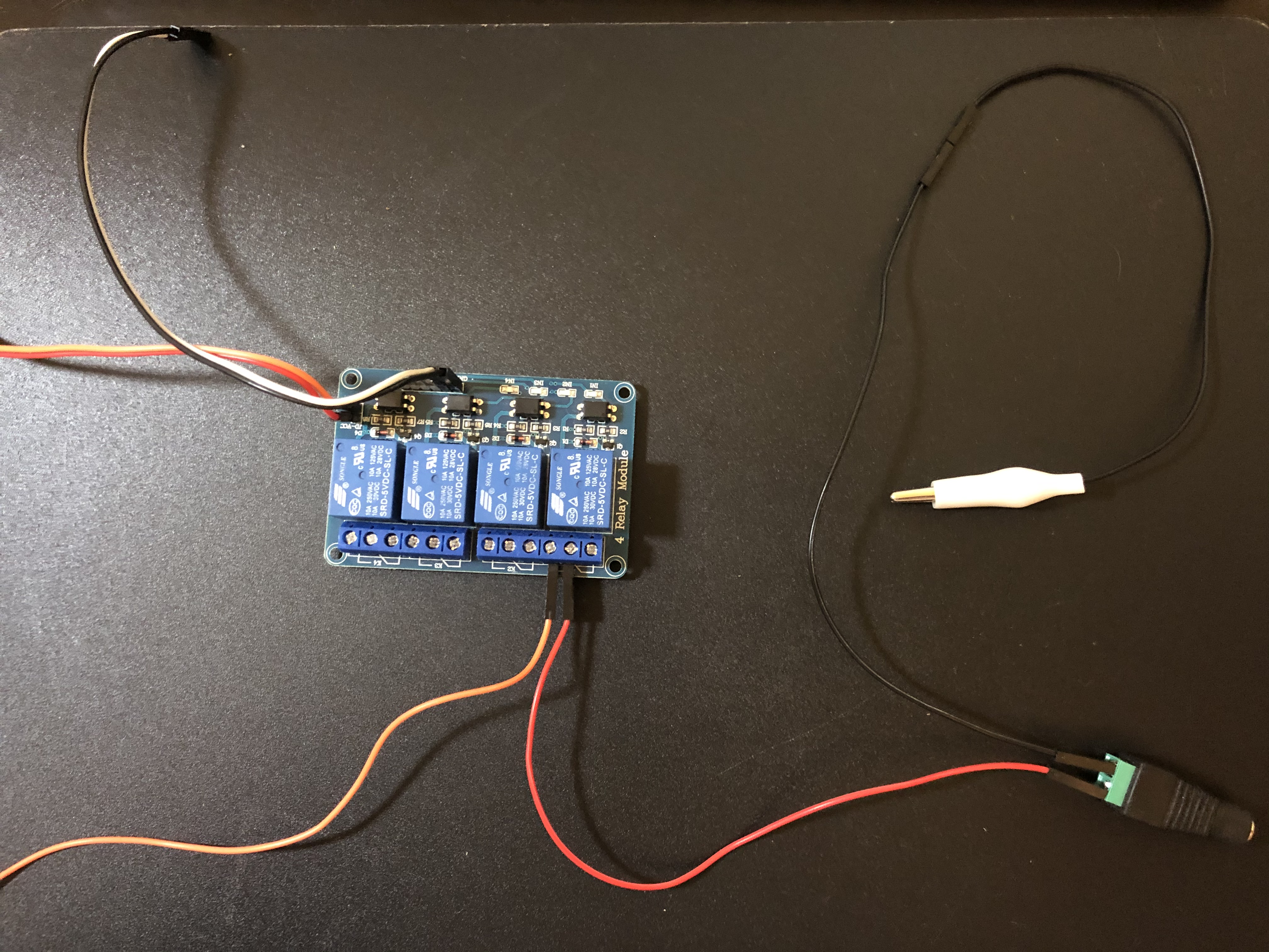
Grab your DC power jack and attach male to male jumper wires to the end of the DC jack (you will need to screw in the wires into the jack, make sure to not tighten them too much).
Attach an alligator clip to the end the negative (black) wire on the DC jack.
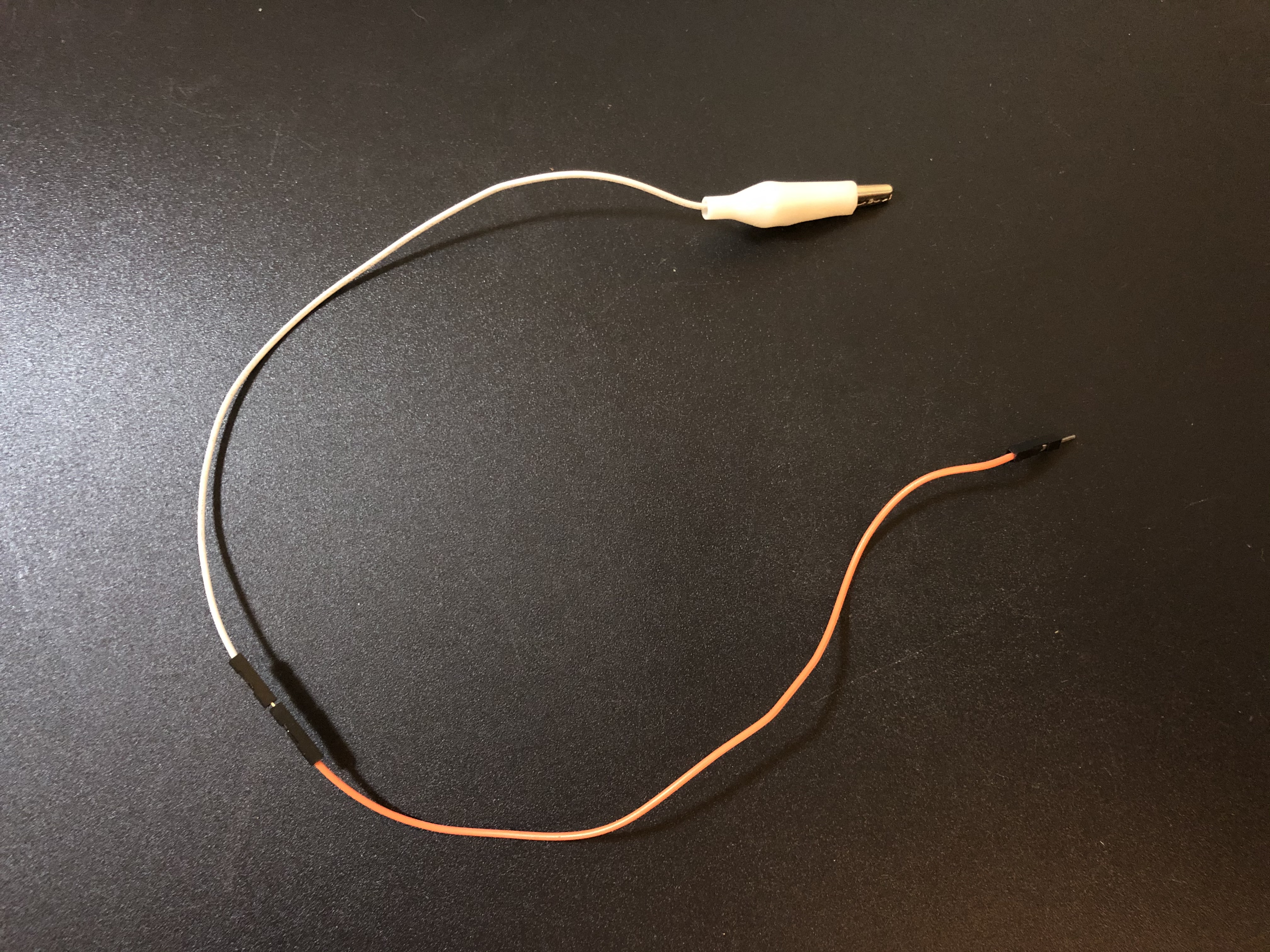
Grab another alligator clip and another male to male jumper wire and connect them together.
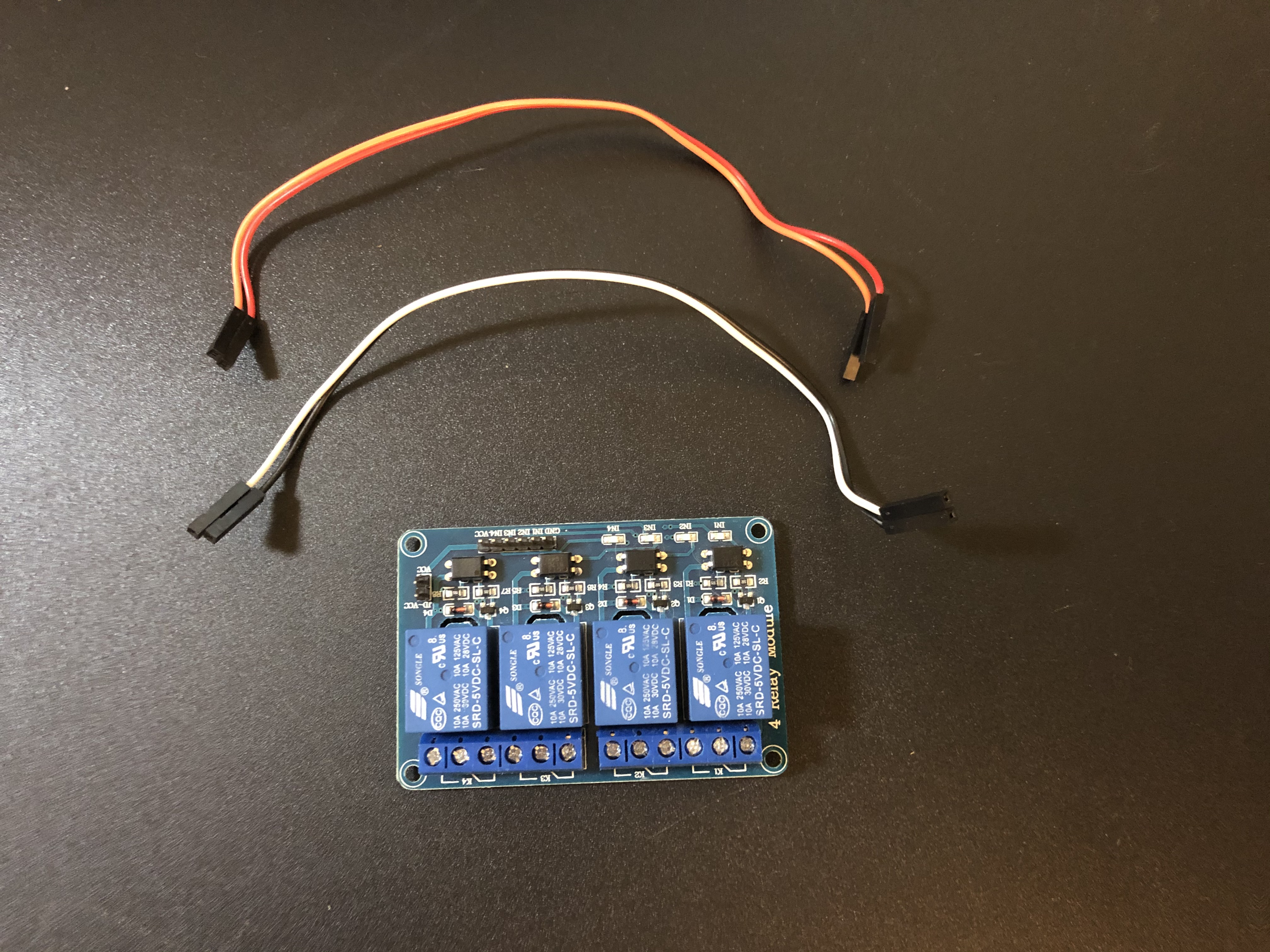
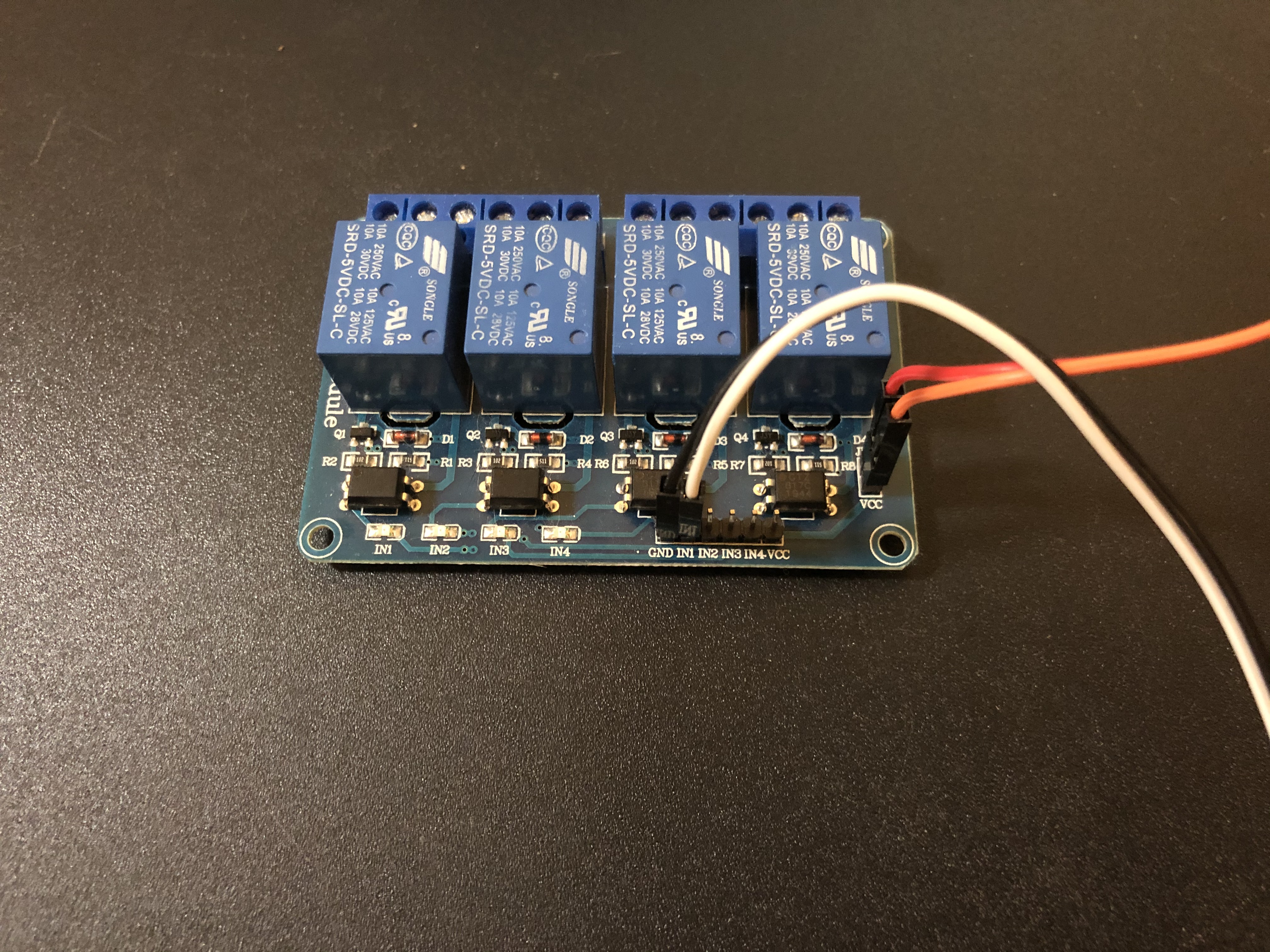
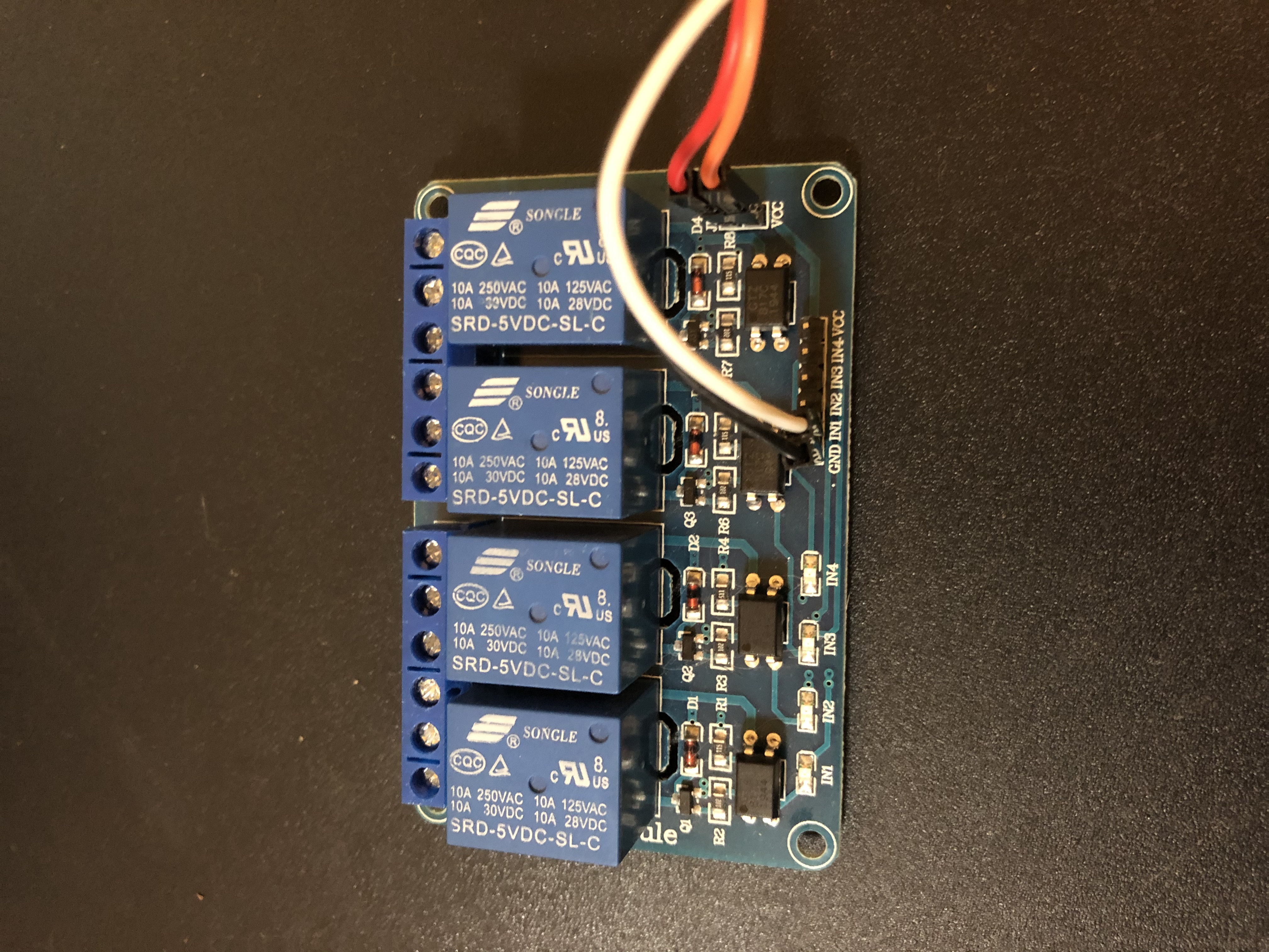
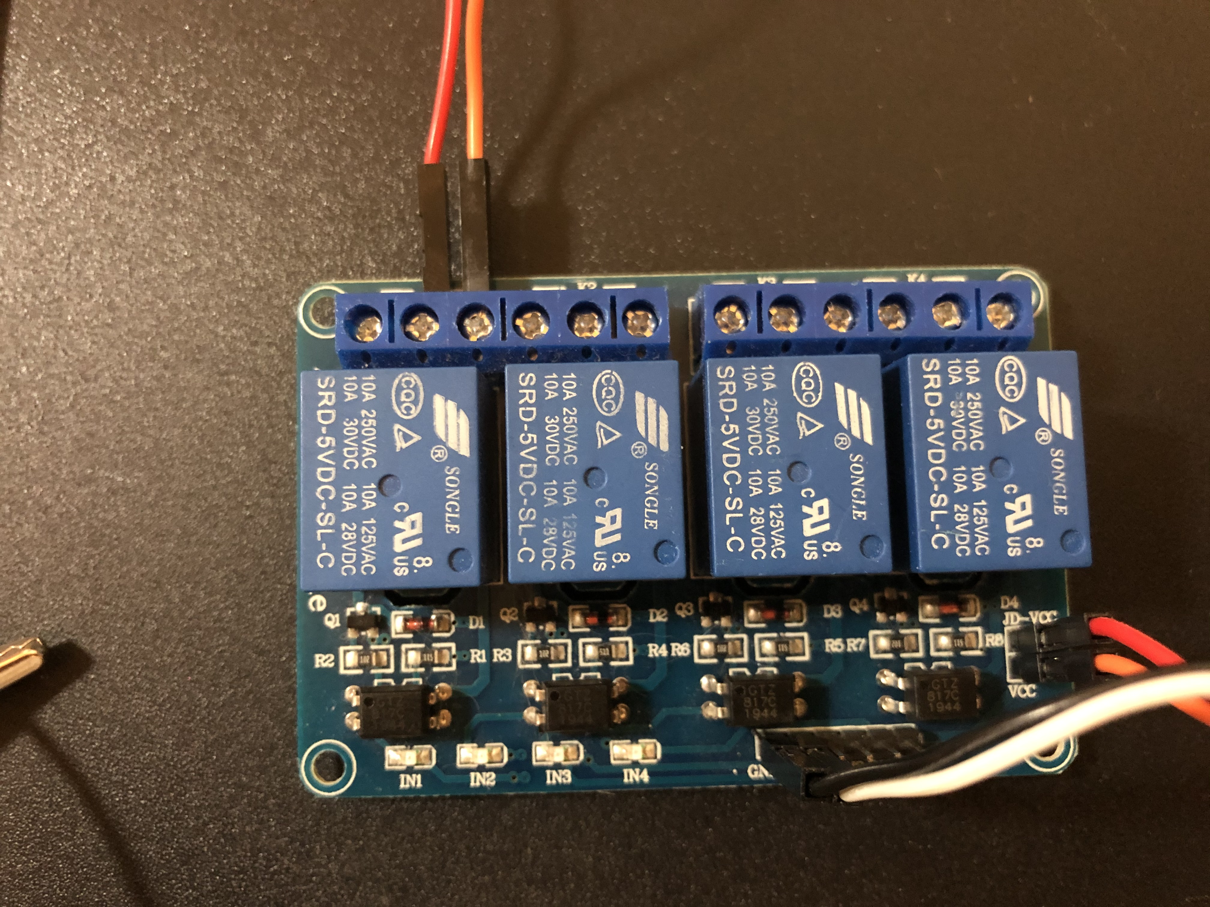
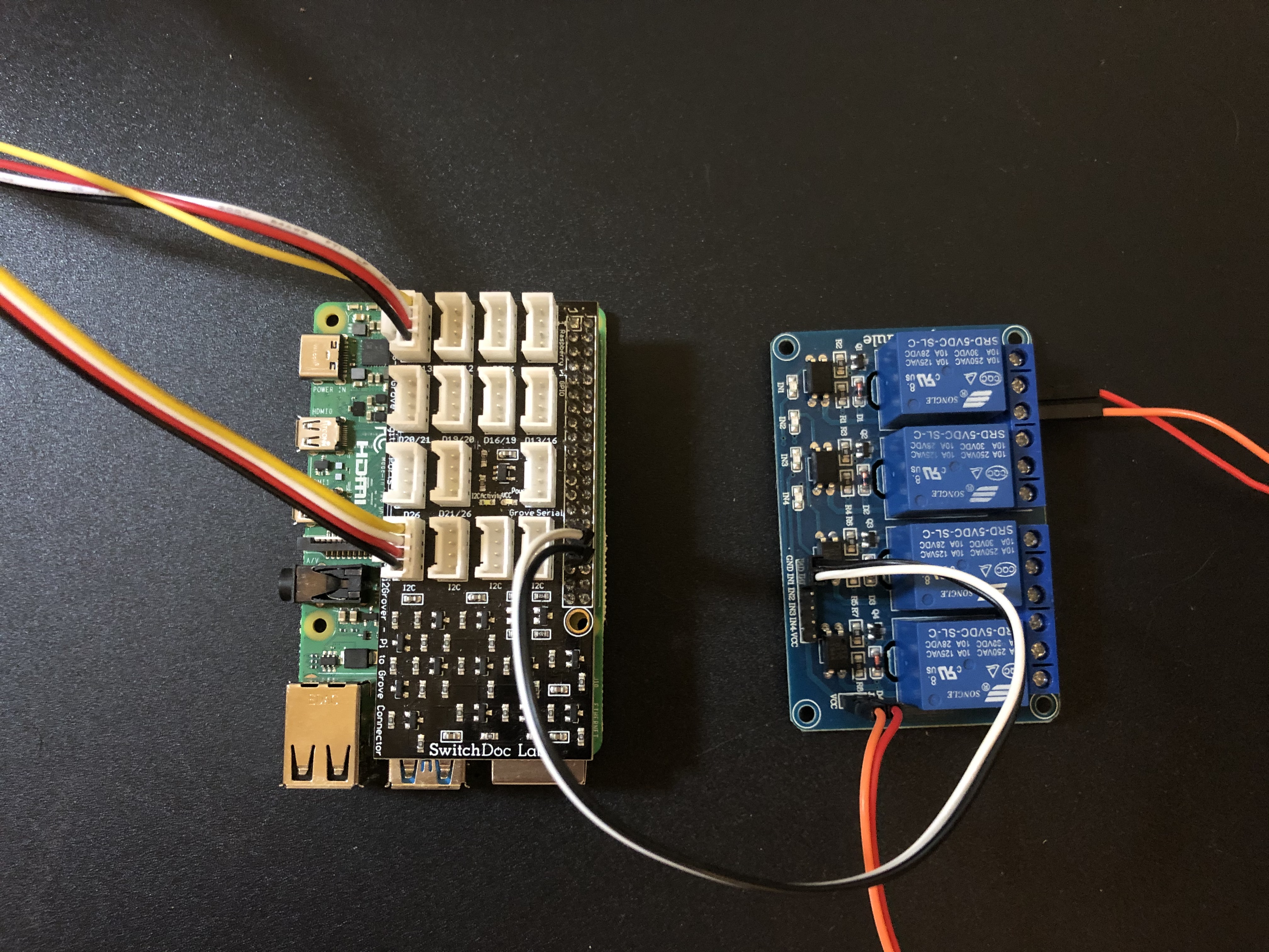
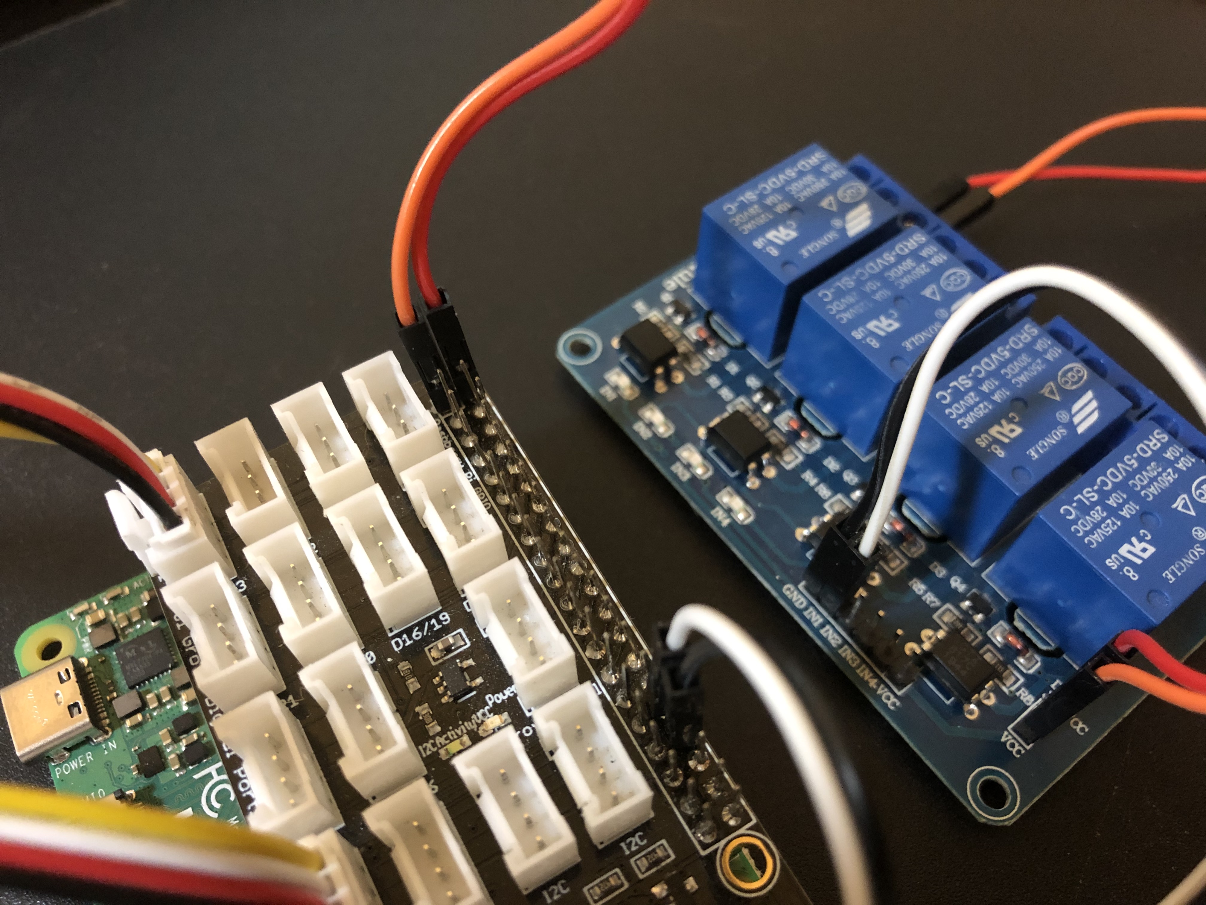
Now grab two female to female jumper wires and connect them to the Relay.
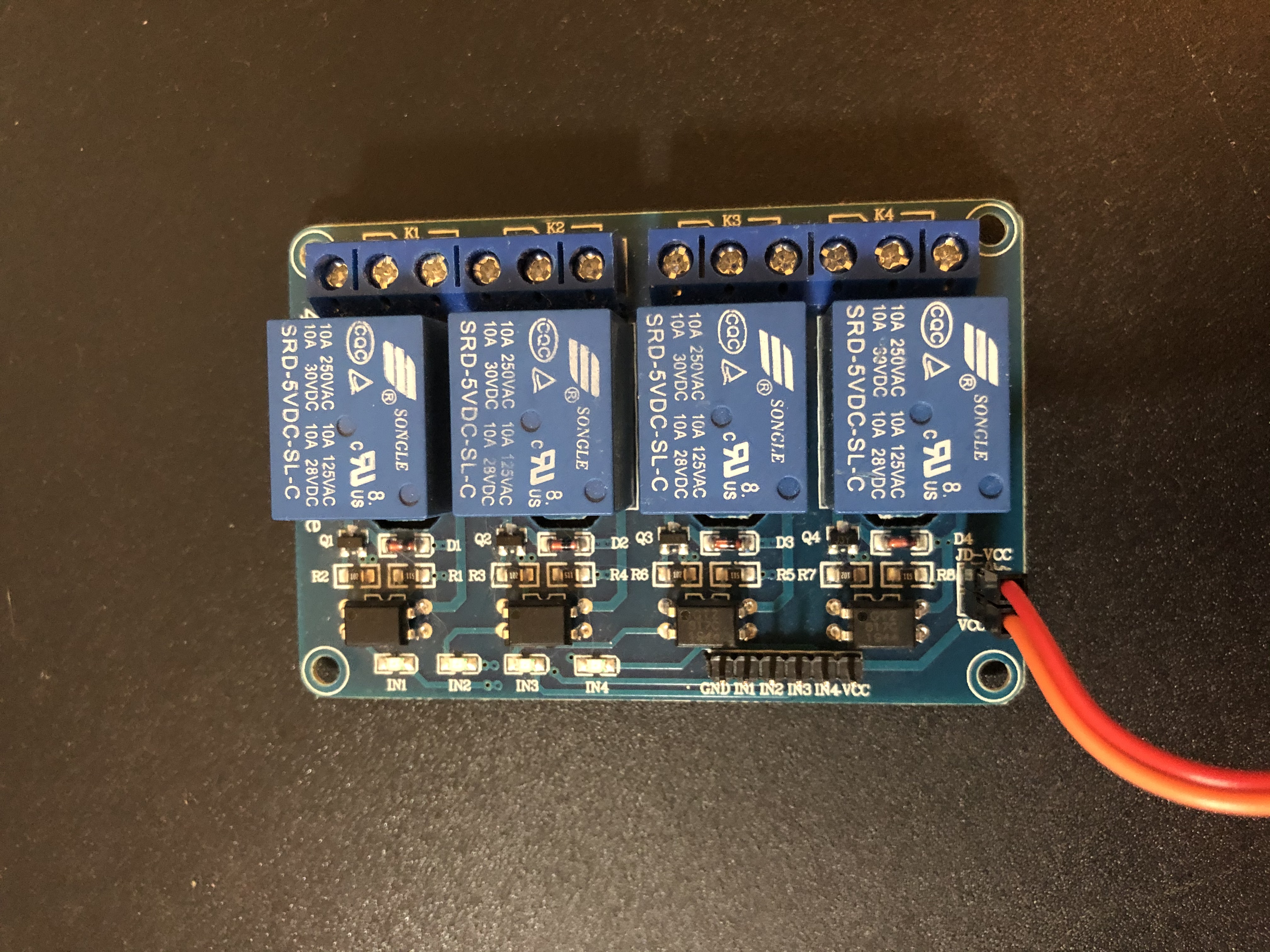
Grab one female to female jumper wire and connect it to the “JD_VCC” and “VCC” pins on the relay.
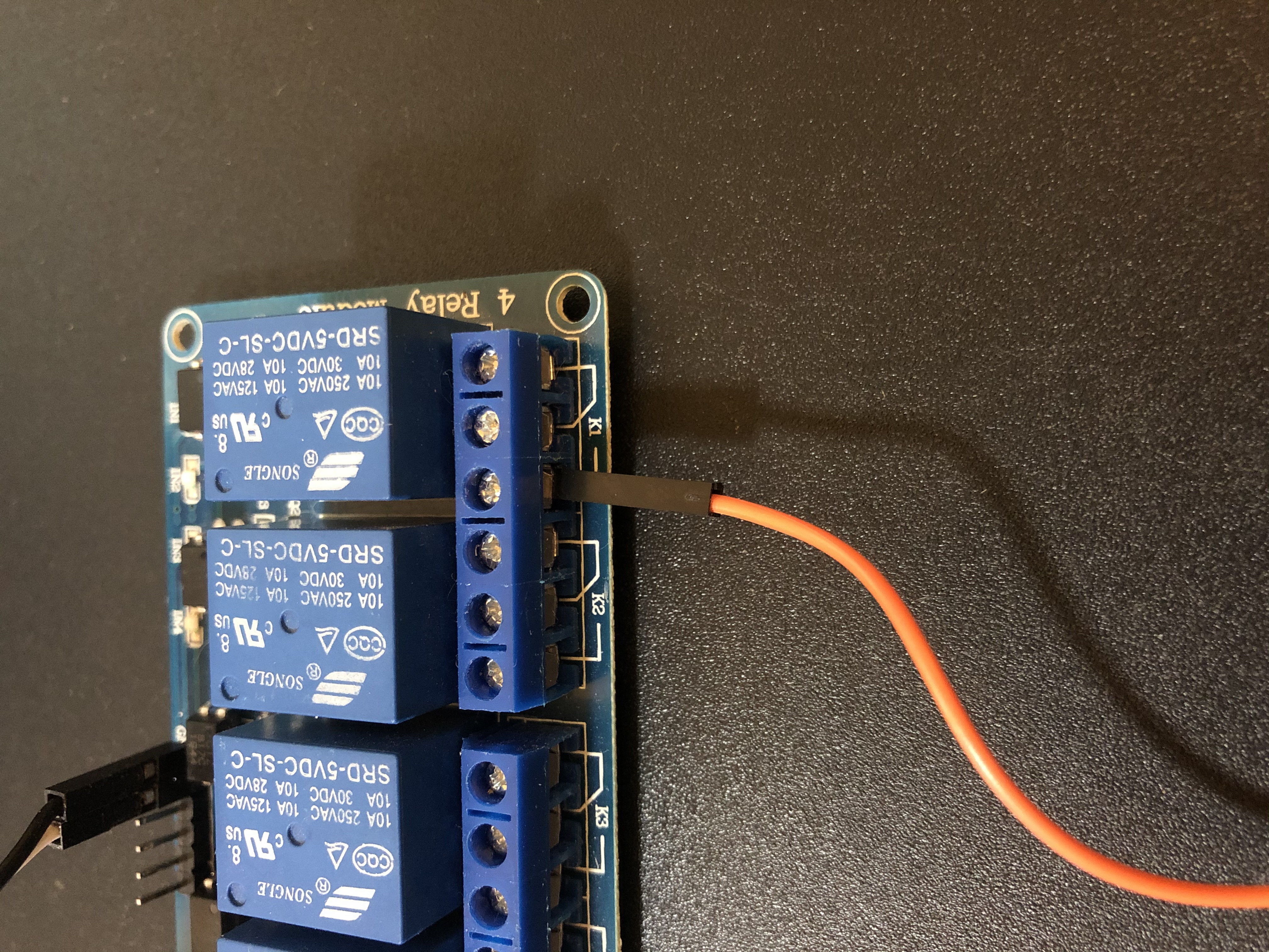
Grab the other female to female jumper wire and connect it to the pins labeled “GND” and “IN1” on the relay.
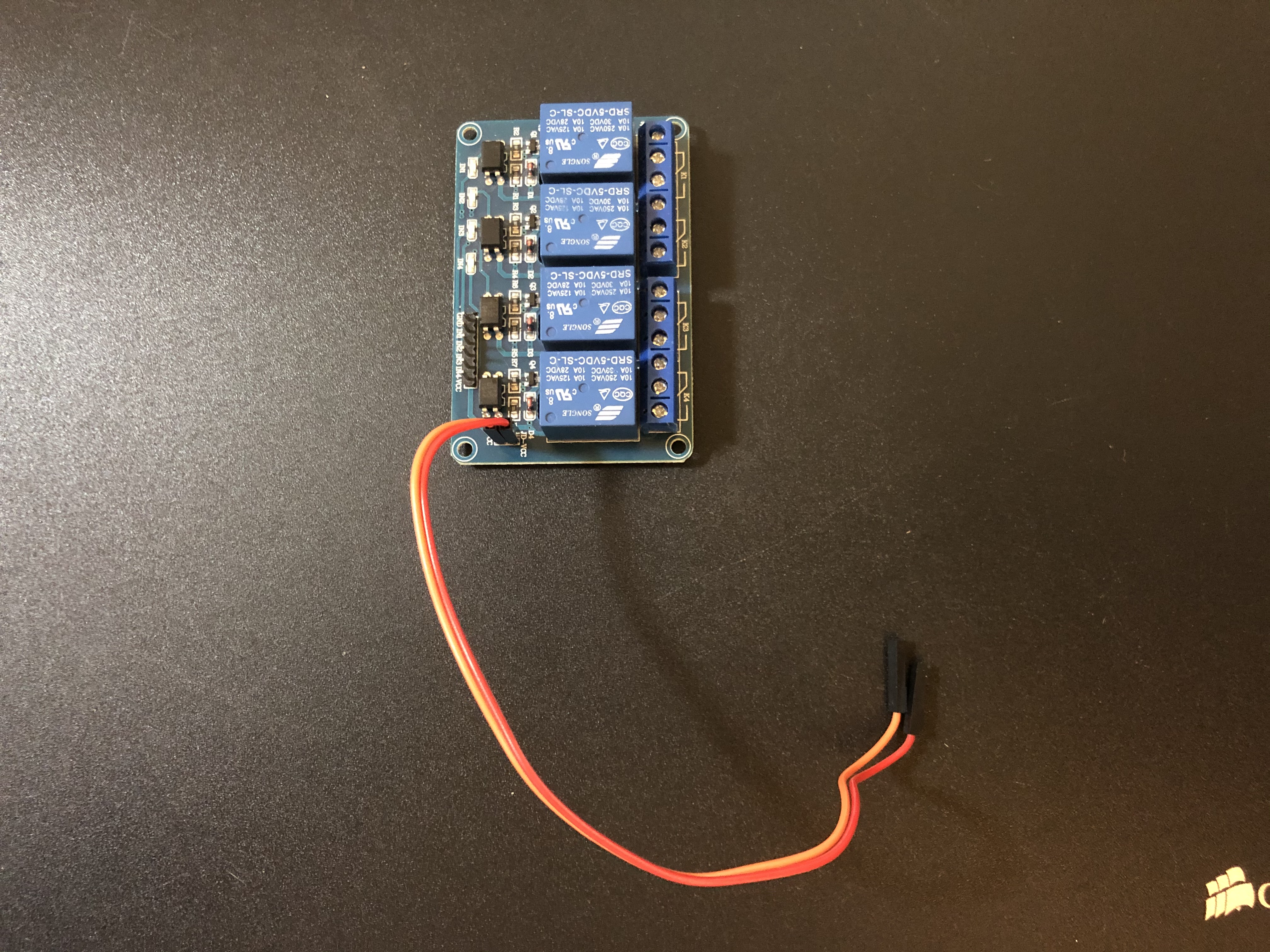
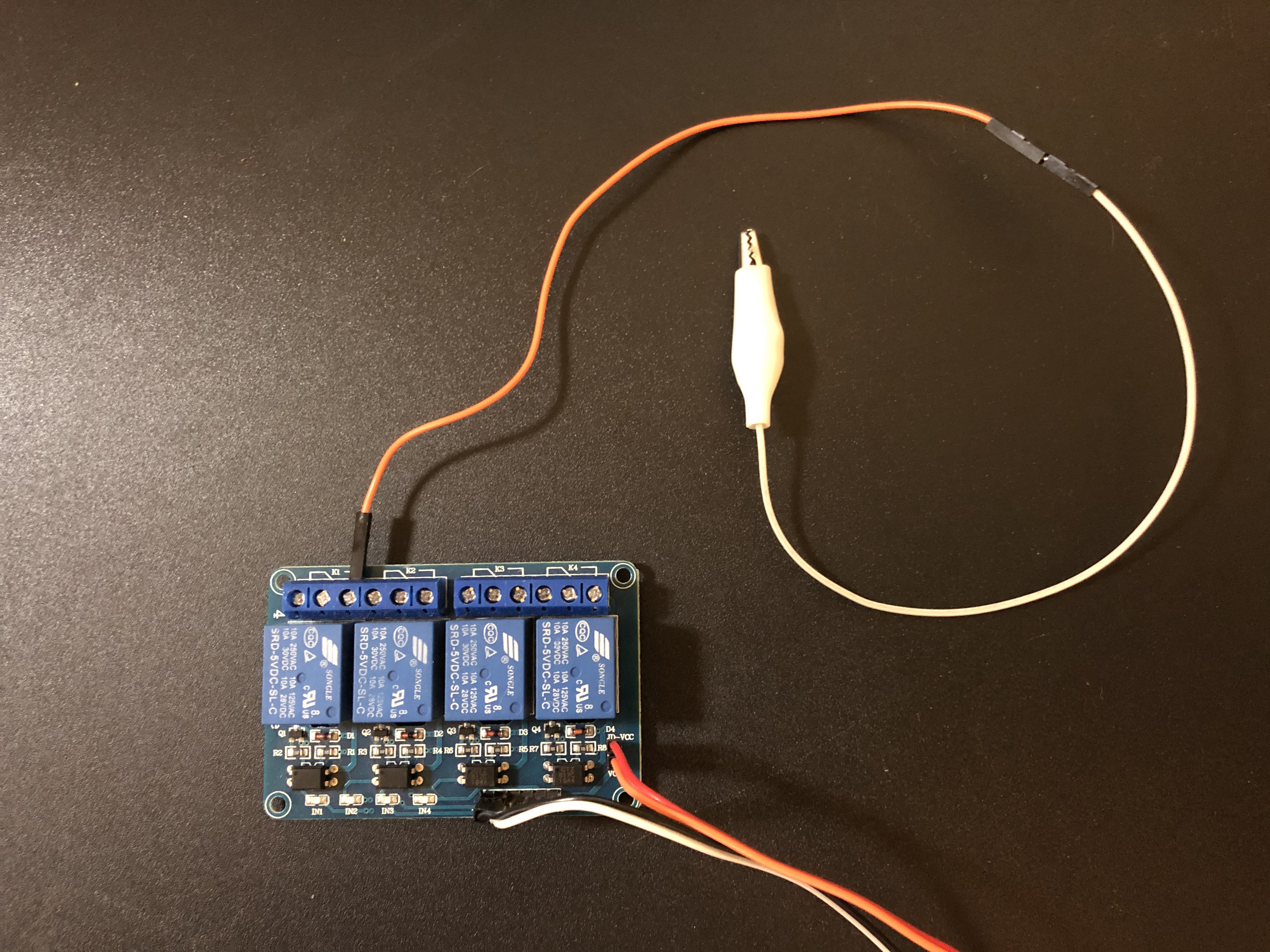
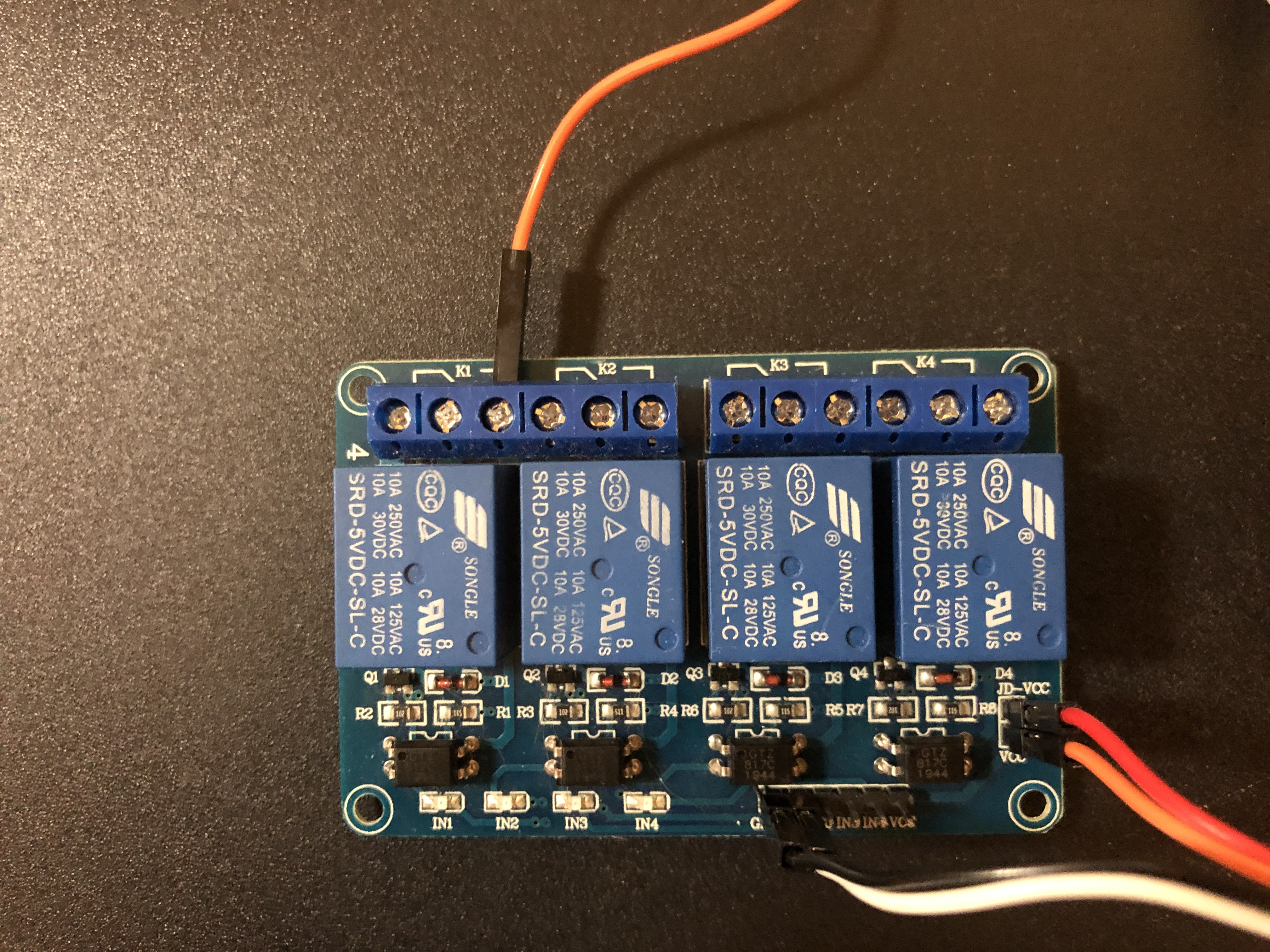
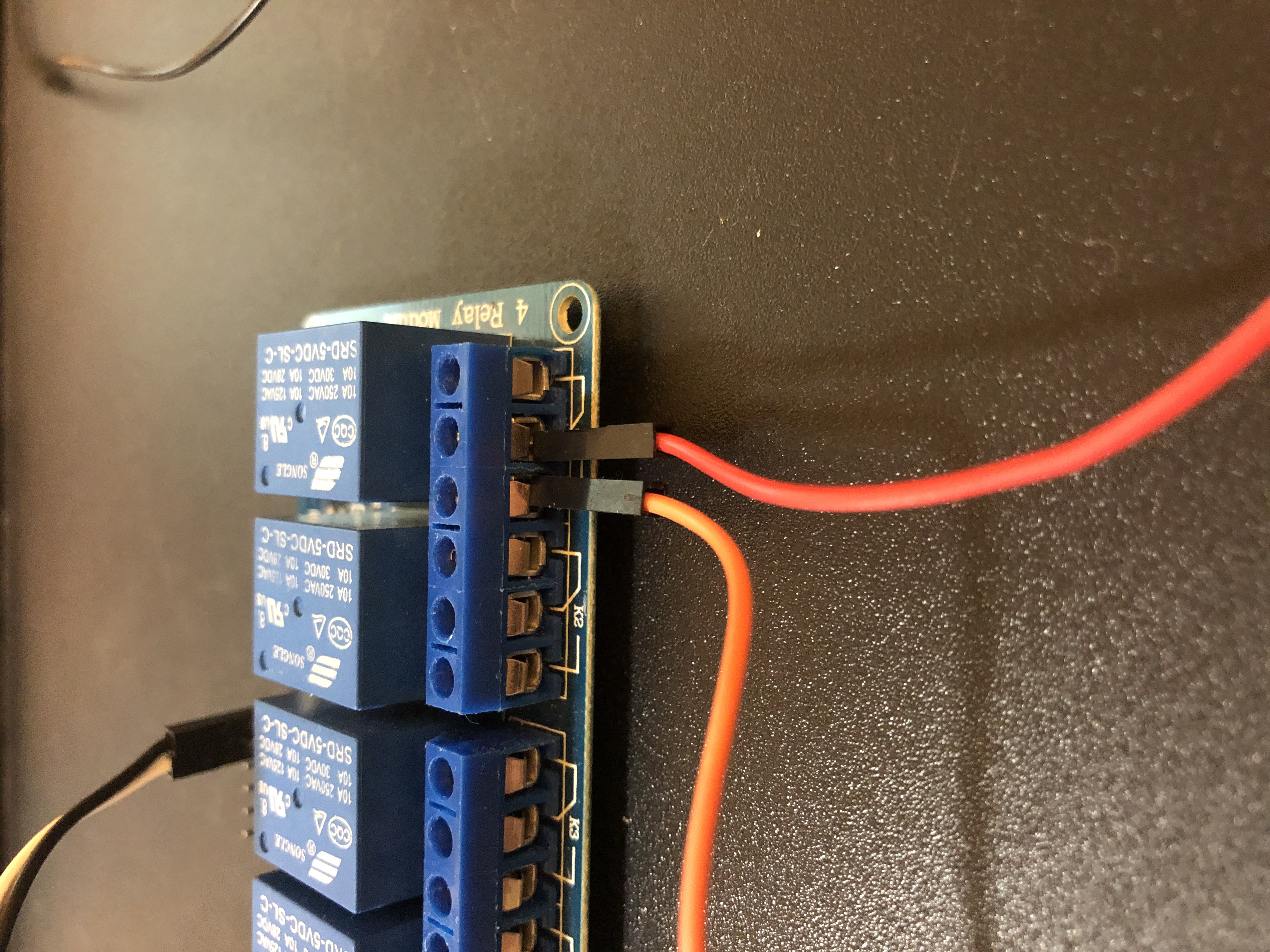
Now grab the alligator clip wire extension that is not connected to the DC jack and screw it into the relay module labeled “K1”
Grab the other alligator clip that is connected to the DC jack and attach it beside the first alligator clip on the relay module labeled “K1”
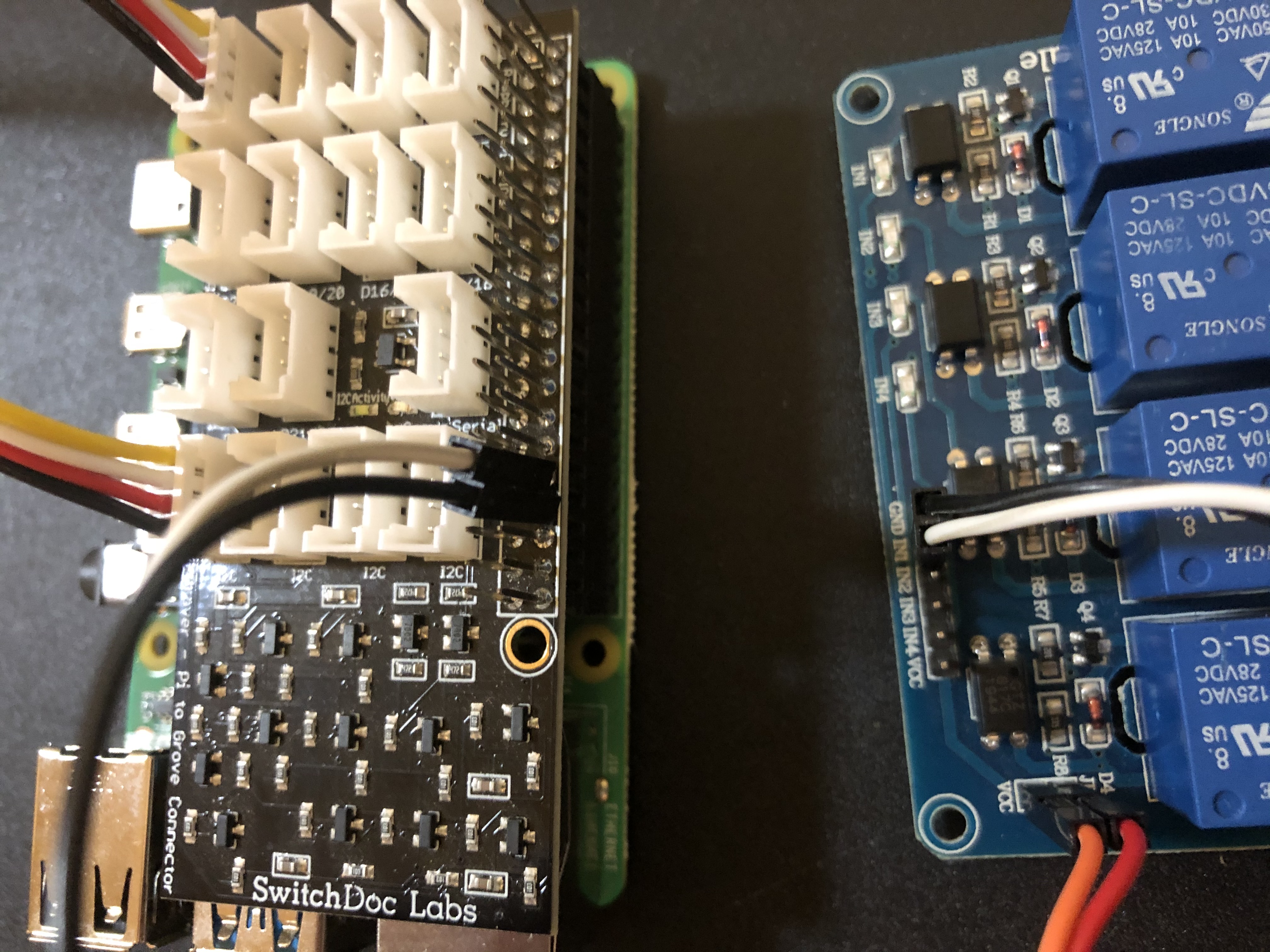
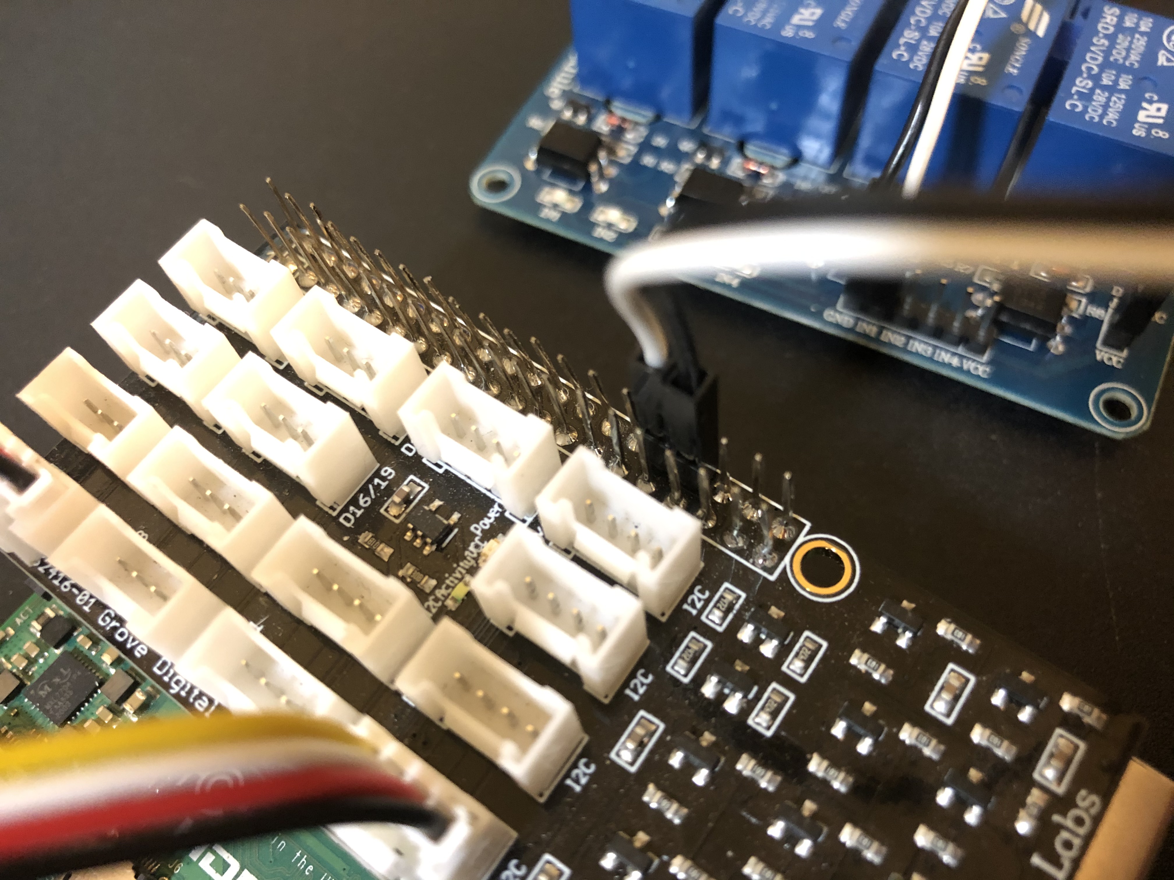
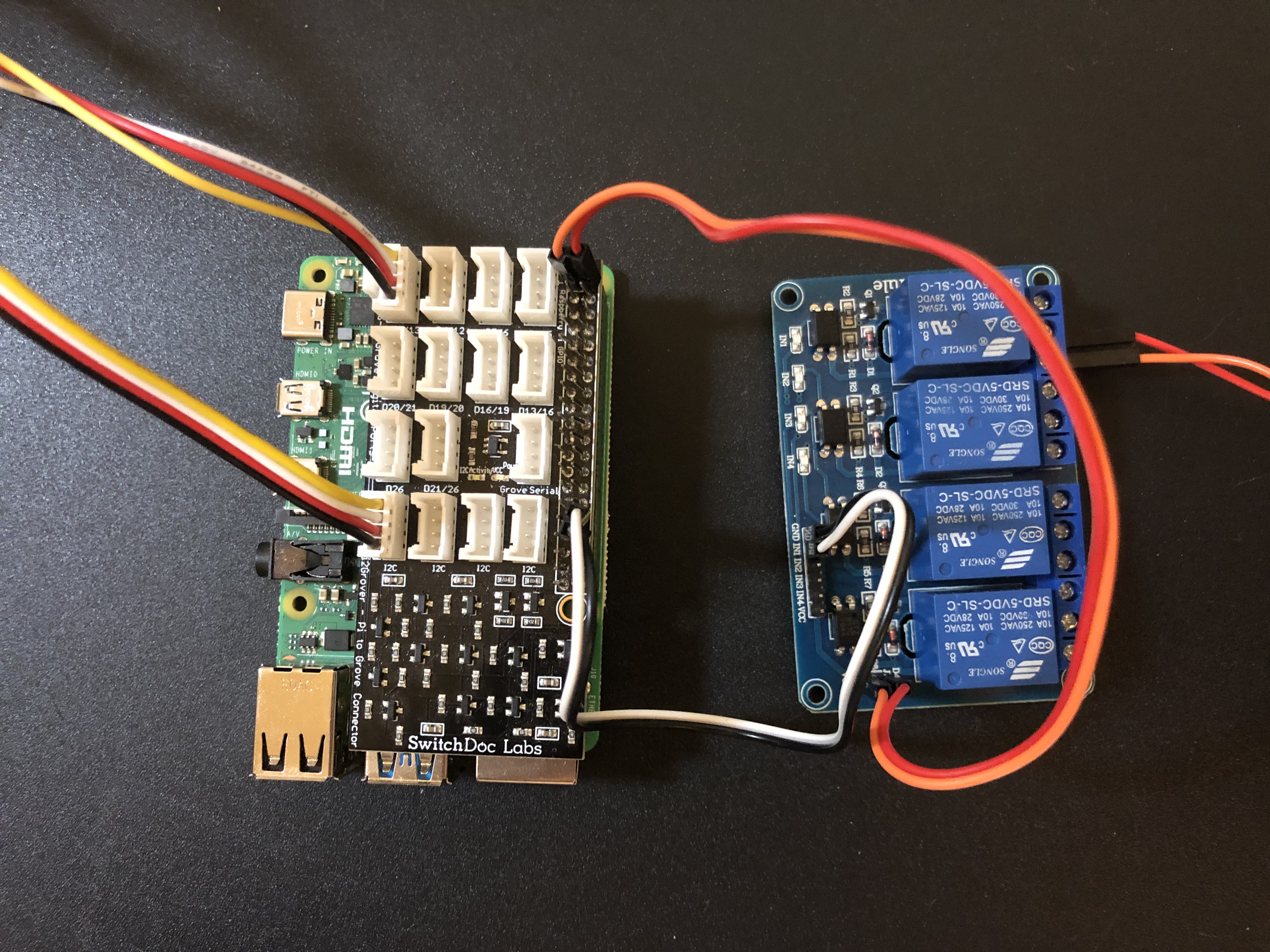
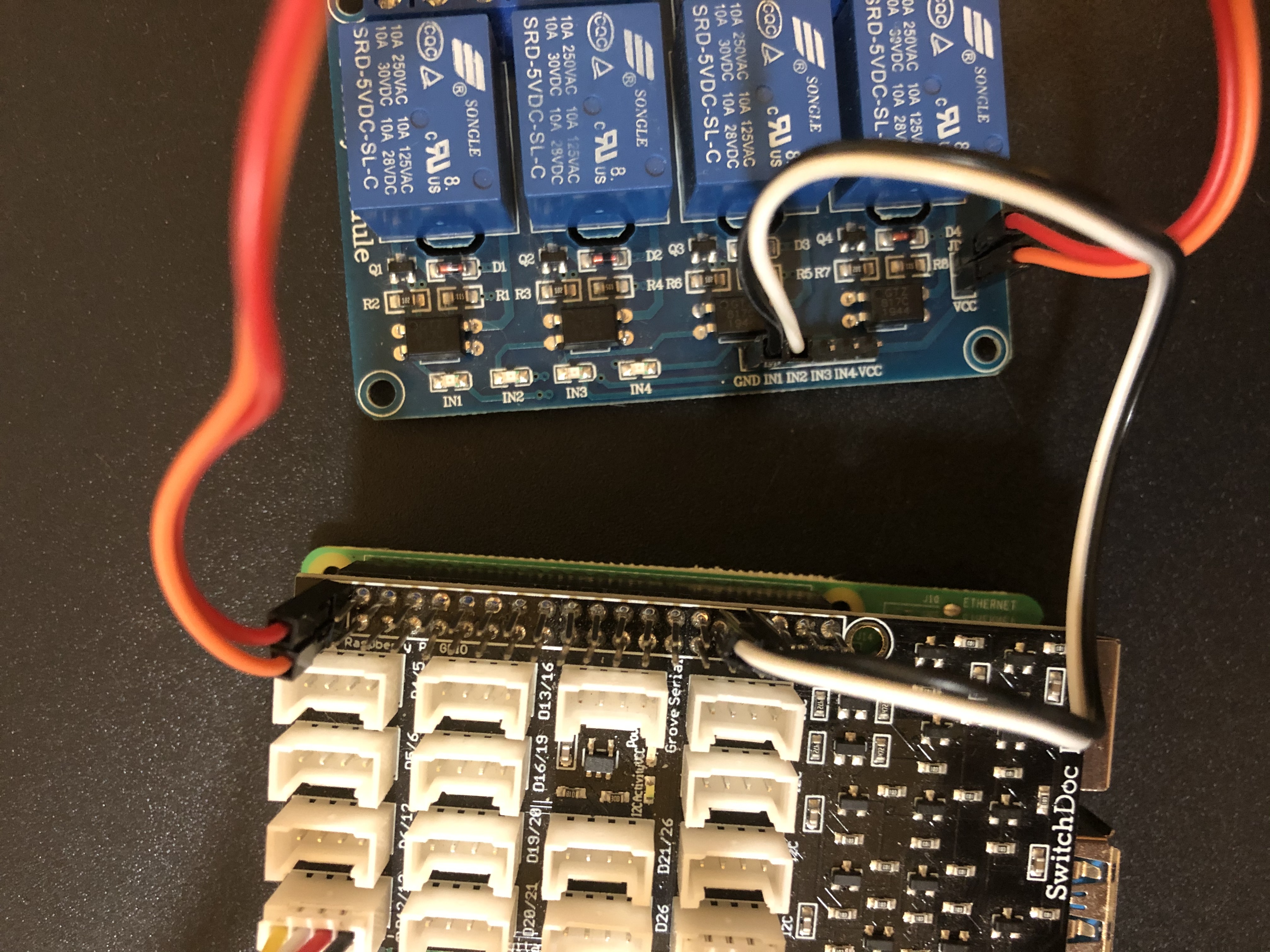
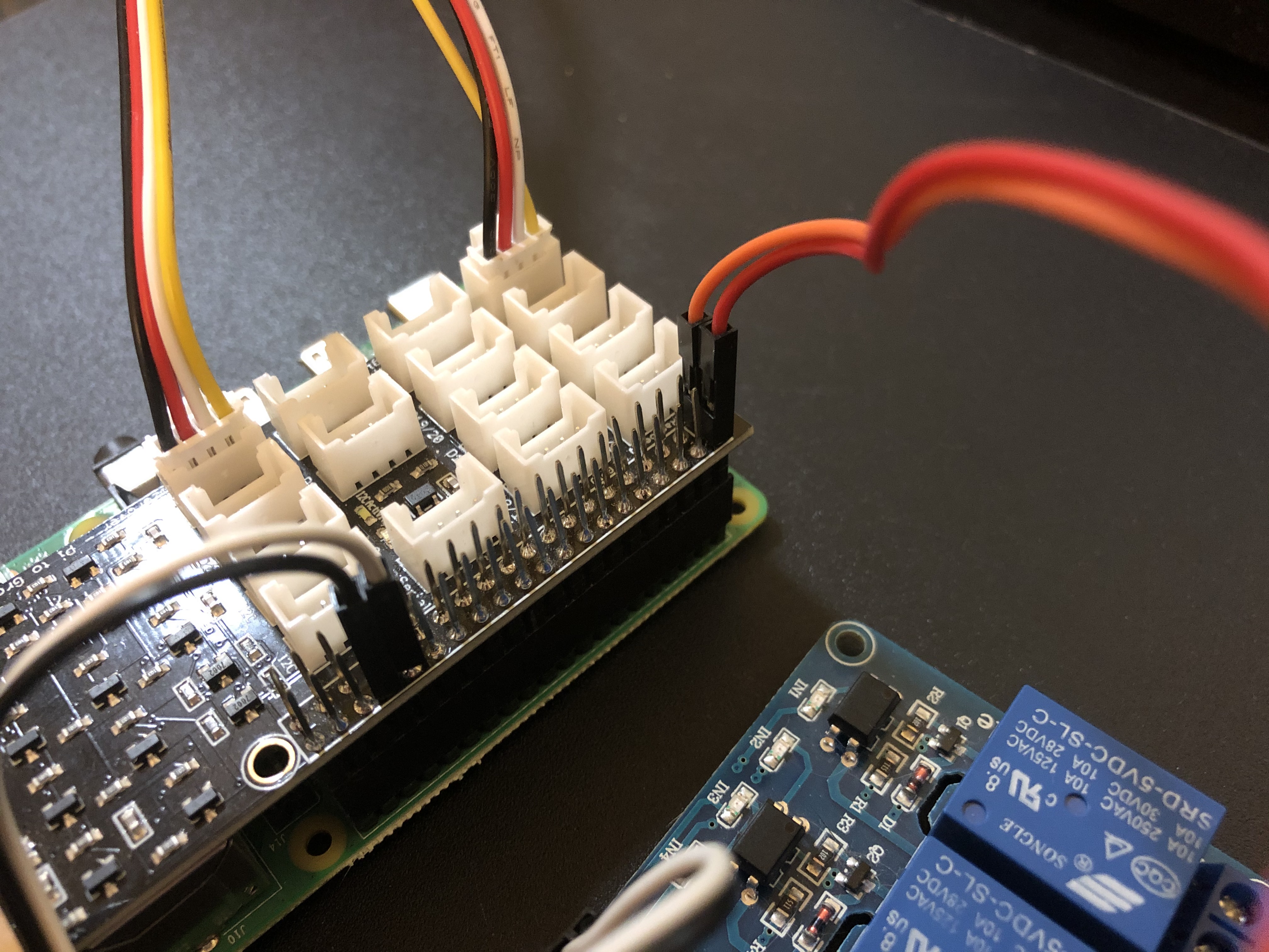
Now attach the female ends from the wires on the relay board to the pins on from the Pi2Grover attached to the Pi.
Attach the “GND” wire from the relay to physical pin 34 on the Pi and attach the “IN1” wire from the relay to physical pin 32 (GPIO 12) on the Pi2Grover.
Attach the “VCC” wire from the relay into physical pin 1 on the Pi and attach the “JD_VCC” wire from the relay to physical pin 2 on the Pi2Grover.
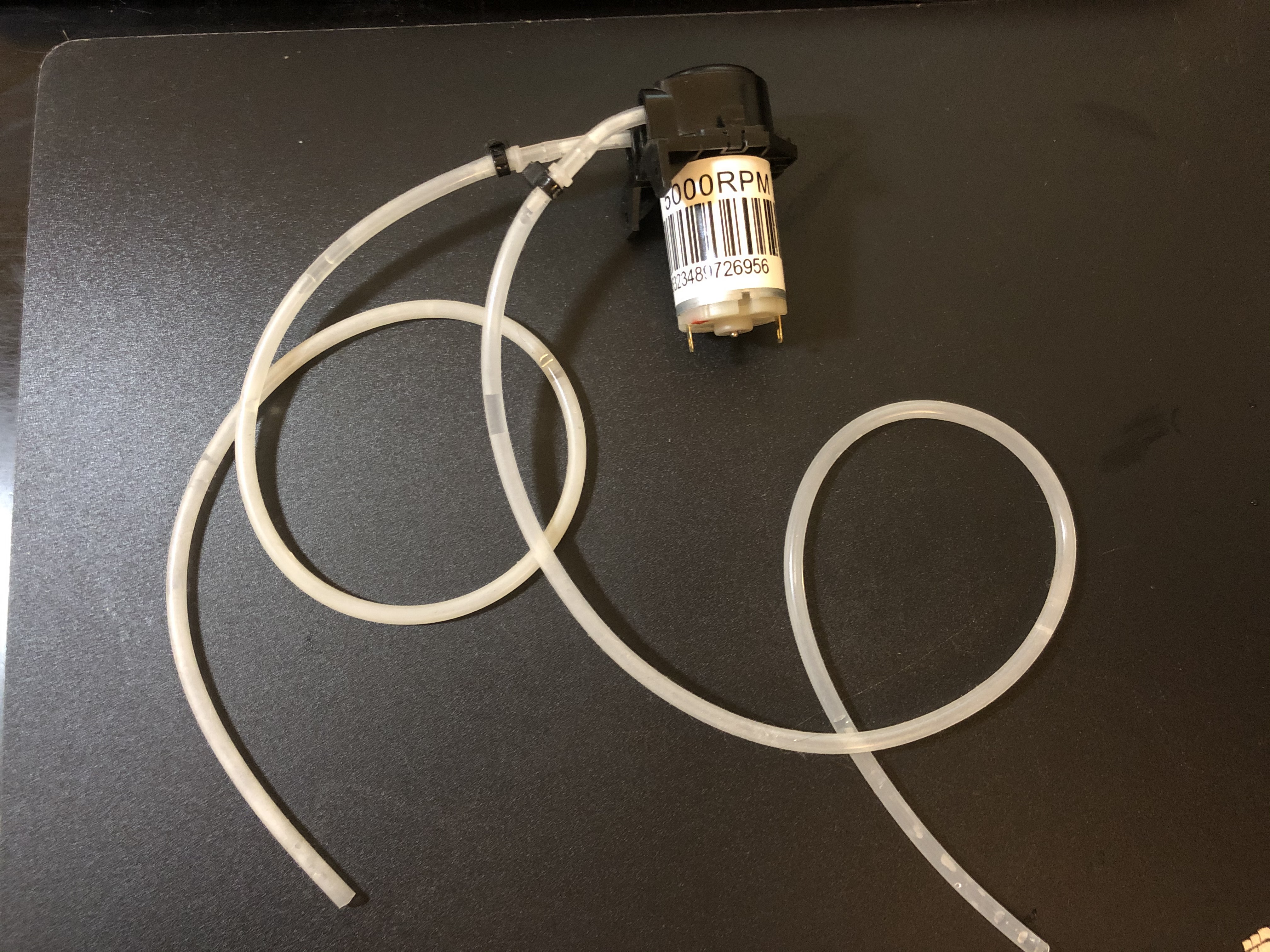
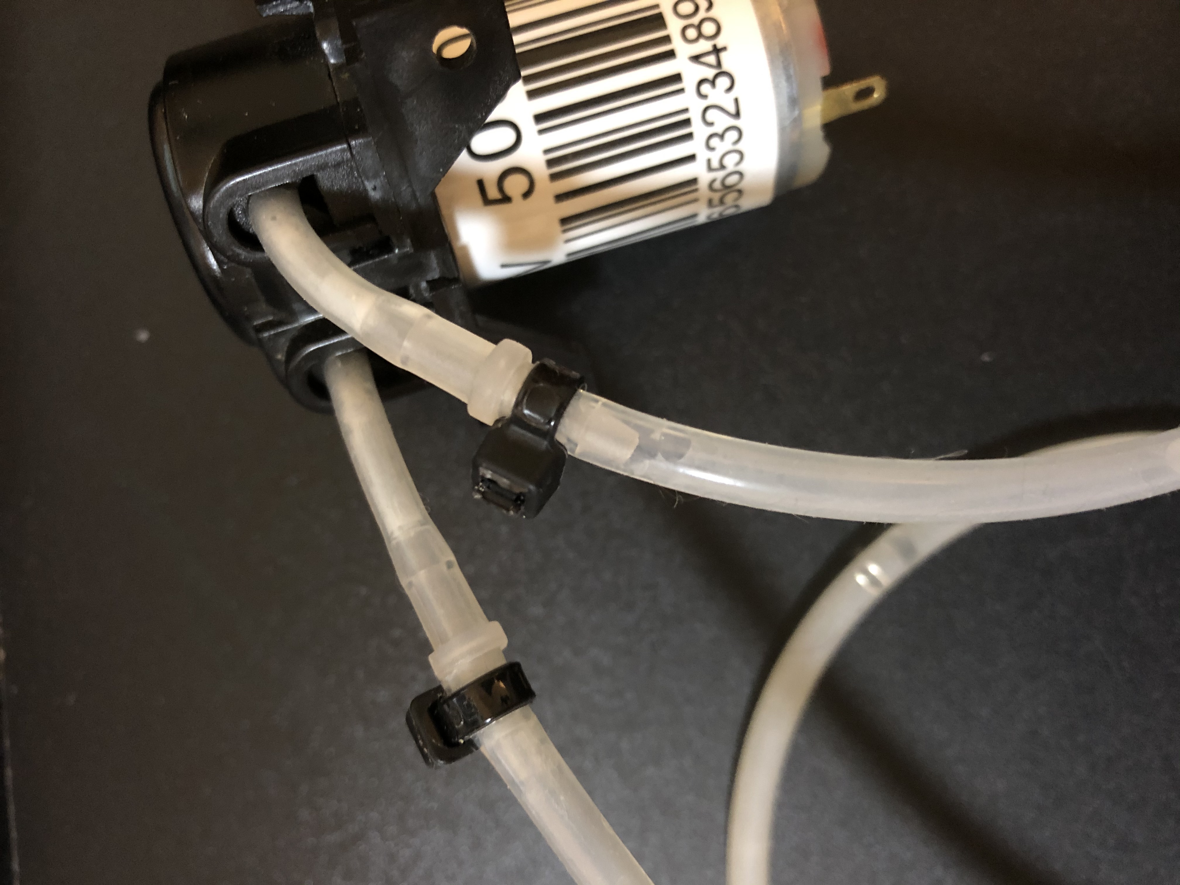
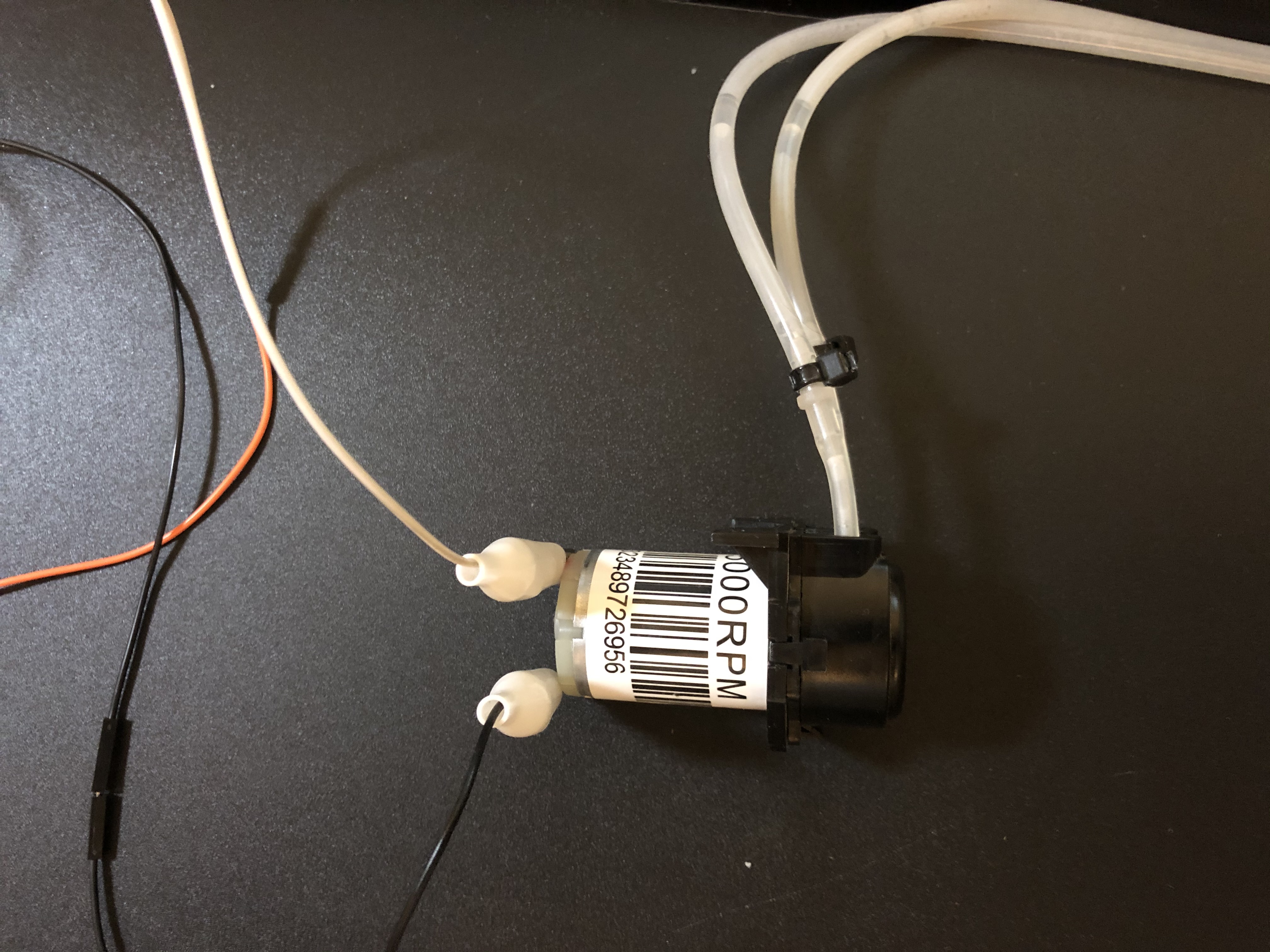
Attach your desired length of silicone tubing with zip ties to the ends of the water pump (do not overtighten the zip ties because that can restrict water flow).
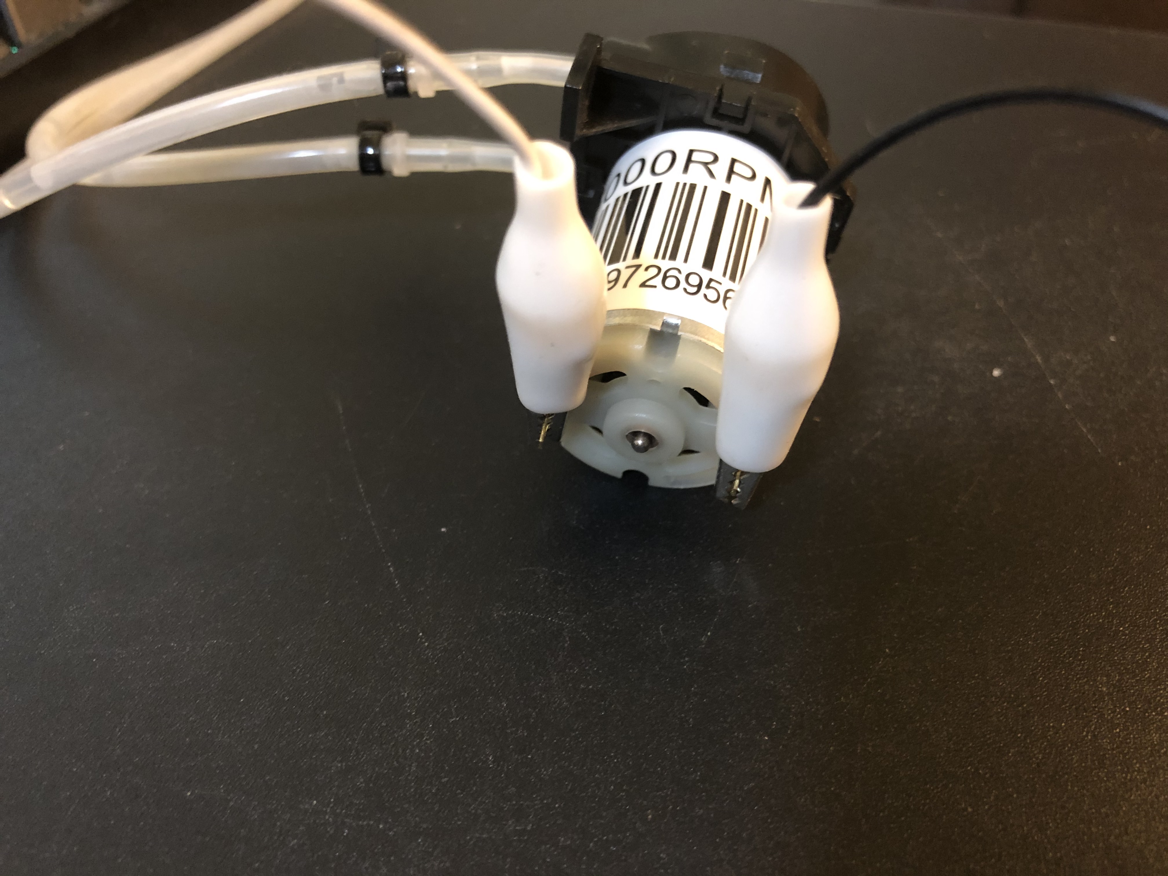
Attach the ends of the alligator clips connected to the relay to the prongs sticking out from the water pump. For this part, the orientation in which you attach the
alligator clips to the water pump doesn’t matter, it only switches the way in which water flows in and out of the water pump.
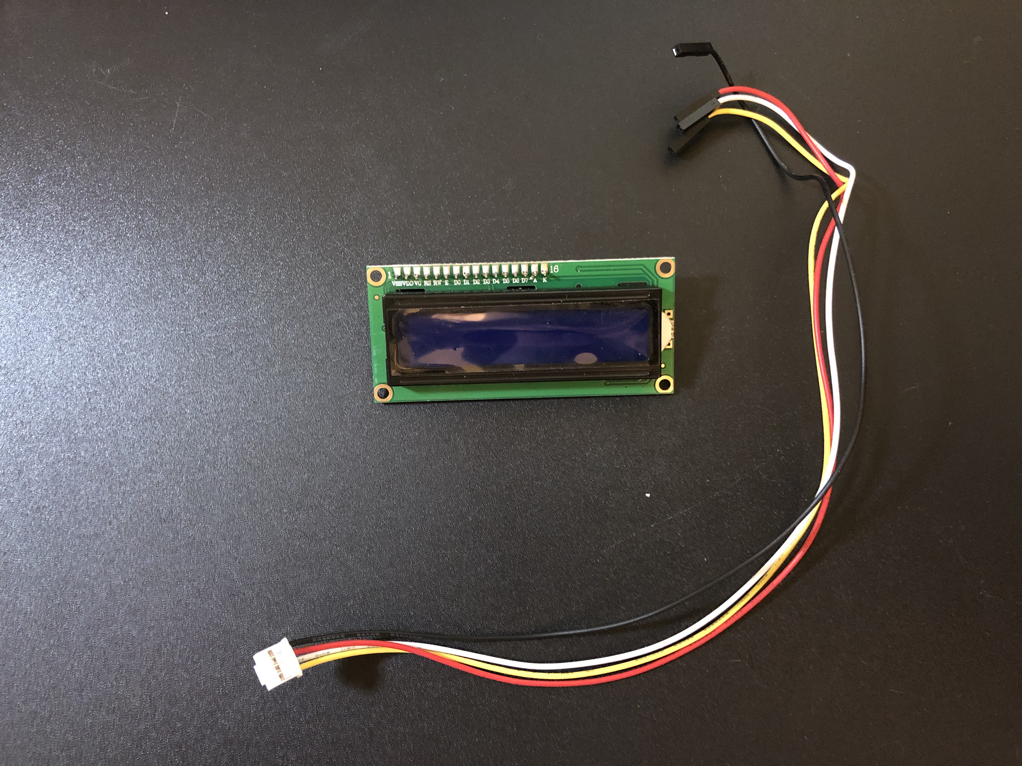
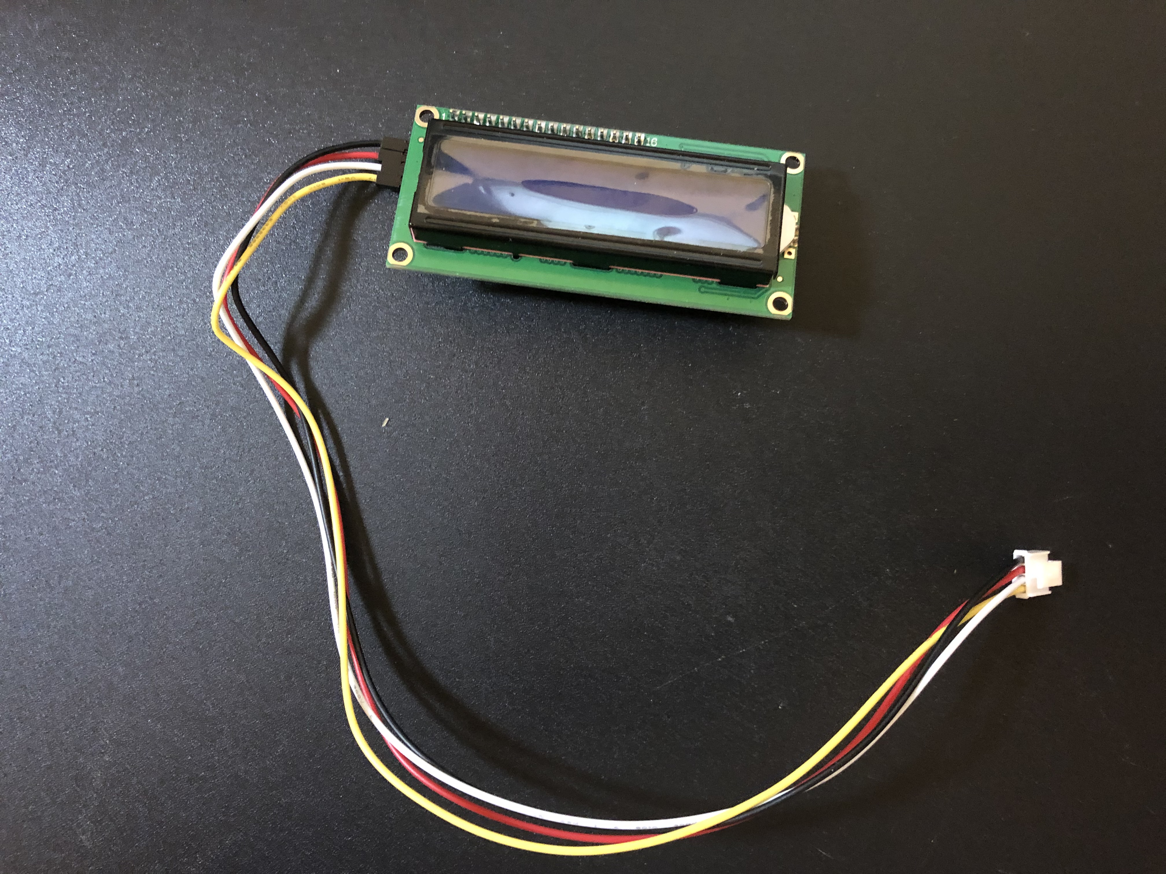
Optional: Attach the LCD to the Raspberry Pi.
Grab a grove 4-pin connector to jumper wires and attach it to the back of your LCD screen.
Attach the black wire from the grove connector to the pin labeled “GND” on the back of the LCD.
Attach the red wire from the grove connector to the pin labeled “VCC” on the back of the LCD.
Attach the white wire from the grove connector to the pin labeled “SDA” on the back of the LCD.
Attach the yellow wire from the grove connector to the pin labeled “SCL” on the back of the LCD.
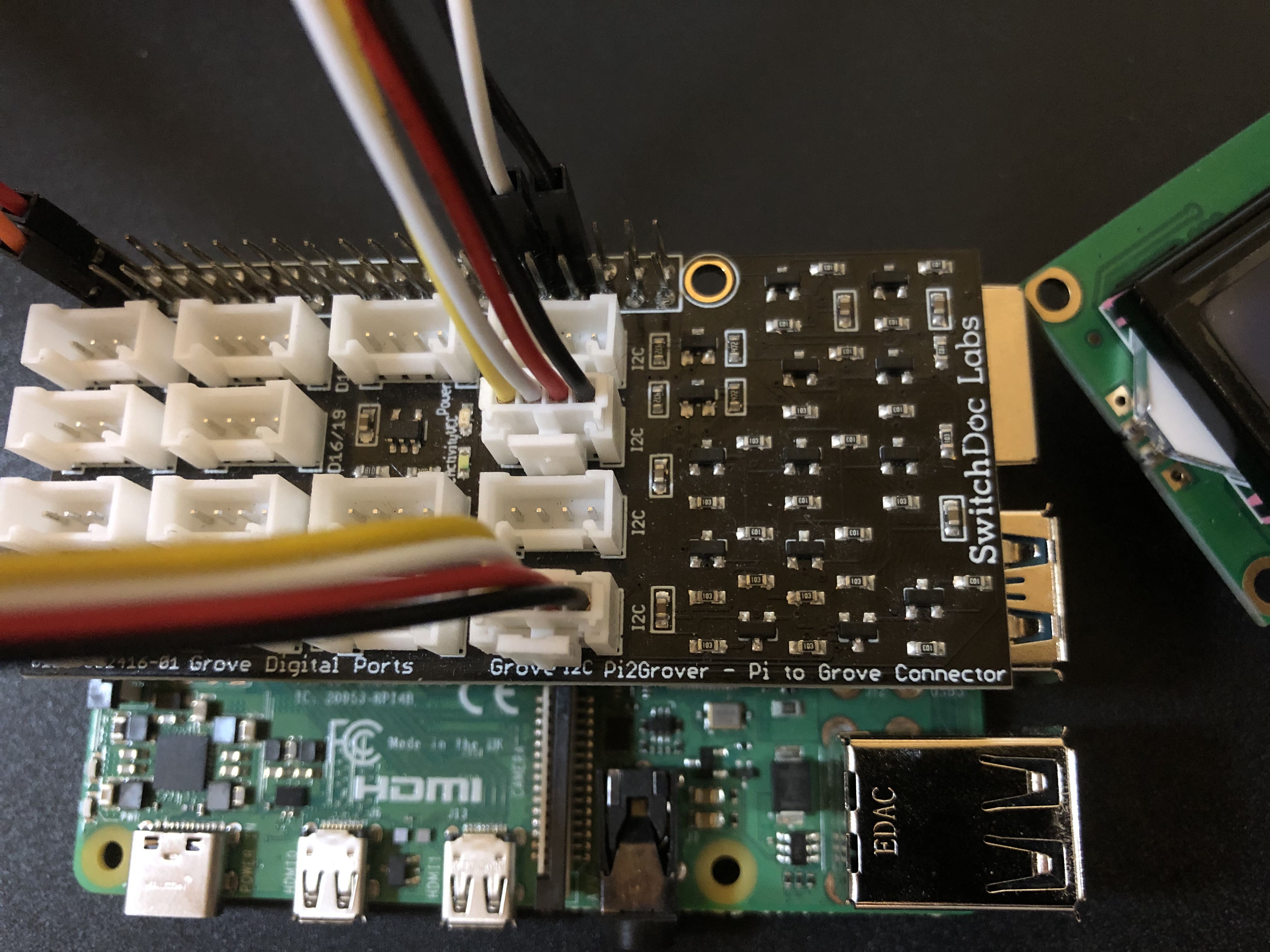
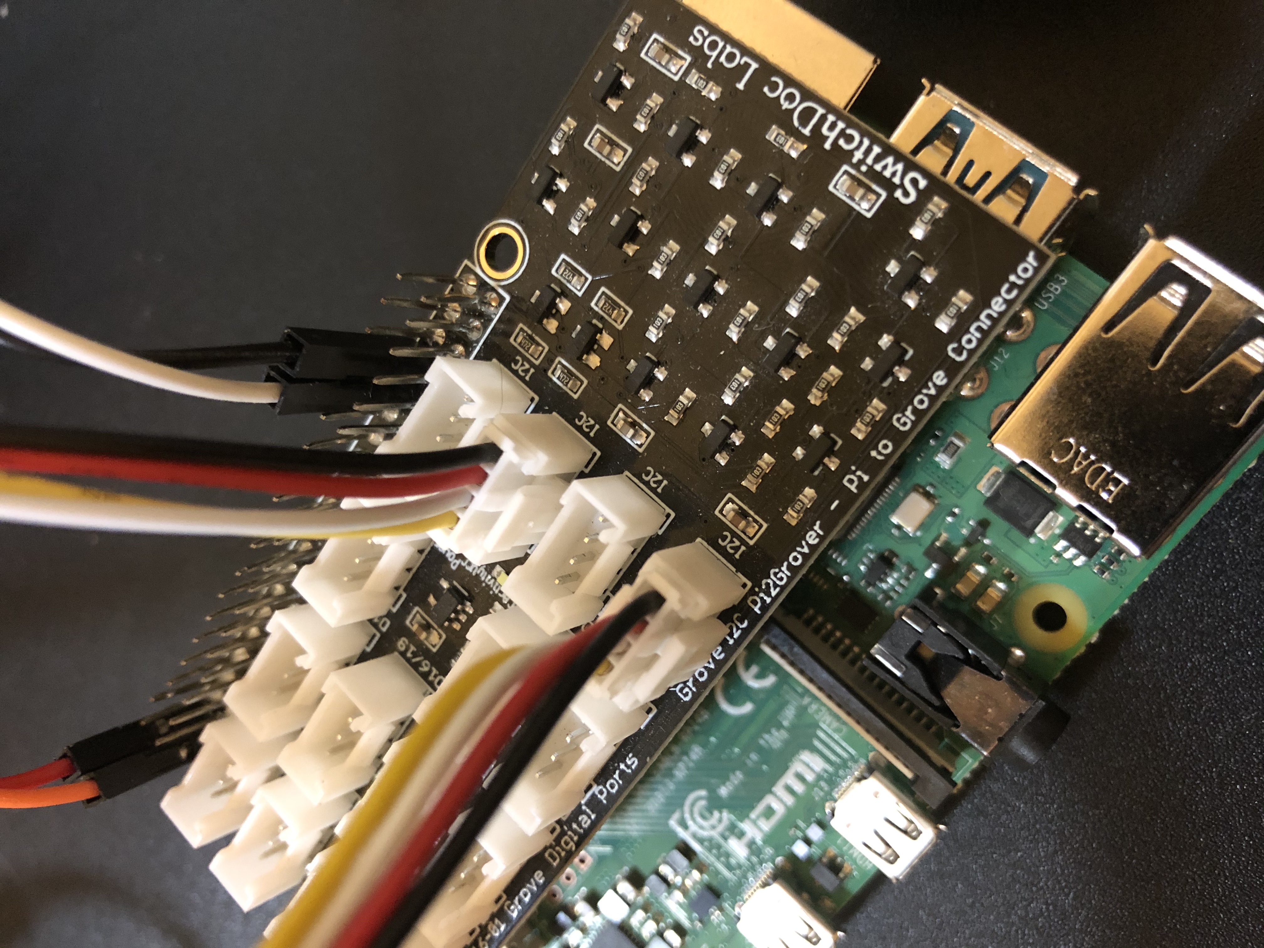
Attach the end of the grove header from the LCD to the “I2C” header on Pi2Grover attached to the Raspberry Pi.